8.1
SVR Virtual Motion Module
8-3
The following table lists application examples of the SVR.
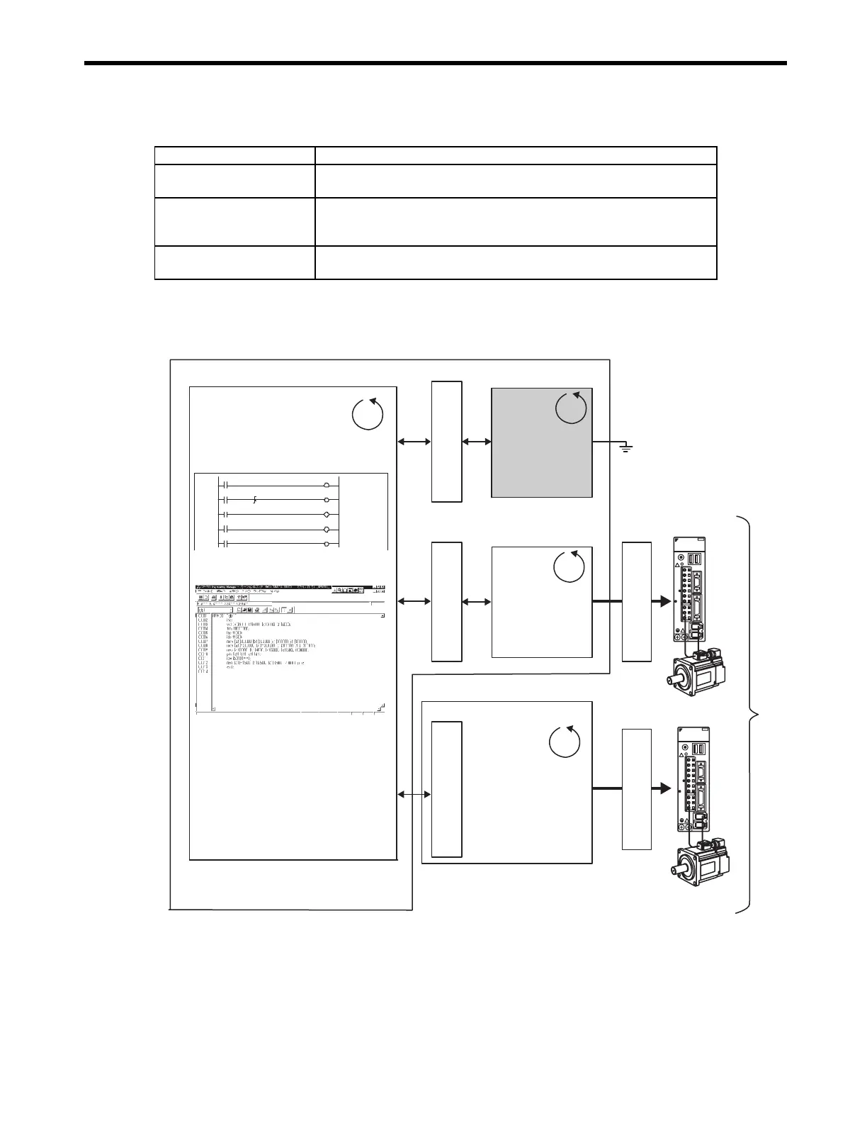
8.1.2 System Configuration
( 1 ) Using the MP2300
Application Example Application Method
Master axis for phase control
Electronic cam or shaft operation can be achieved by using the SVR for the
virtual master axis.
Multi-axis synchronous
control
Multi-axis synchronous control can be achieved by controlling the SVR from a
motion program and then using the ladder program to copy position commands
of the SVR to other axes.
Sine curve commands
If the motion program is used to perform circular interpolation with the SVR, the
axis will operate with a sine curve command.
Motion
Parameters
MP2300
Motion
Parameters
Motion
Parameters
1 0000
IB00000 DB000020 DB000010
IB00000 DB00000 0
IB00001 DB000011
1 0002
1 0005
IB00002 DB000012
1 0007
IB00005 DB000015
1 0009
MECHATROLINK
MECHATROLINK
YASKAWA SERVOPACK
200V
SGDS-01A12A
SW1
CHARGE
C
N
3
A/B
C
N
1
C
N
2
C
N
4
L1
L2
L2C
L1C
B1/
B2
U
V
W
C
N
6
YASKAWA SERVOPACK
200V
SGDS-01A12A
SW1
CHARGE
C
N
3
A/B
C
N
1
C
N
2
C
N
4
L1
L2
L2C
L1C
B1/
B2
U
V
W
C
N
6
High-speed
scan
Virtual servo axes
SVB-01 Motion Module
Optional Module
Ready to run
Start
Holding
Stopped
Reset
Ladder program
Motion program
SERVOPACK
Servomotor
SERVOPACK
Servomotor
High-speed
scan
High-speed
scan
High-speed
scan
SVR Virtual
Motion
Module
SVB Motion
Module
Real servo axes
WWW.NNC.IR