2.2
SVA-01 Module Specifications and Connections
2-23
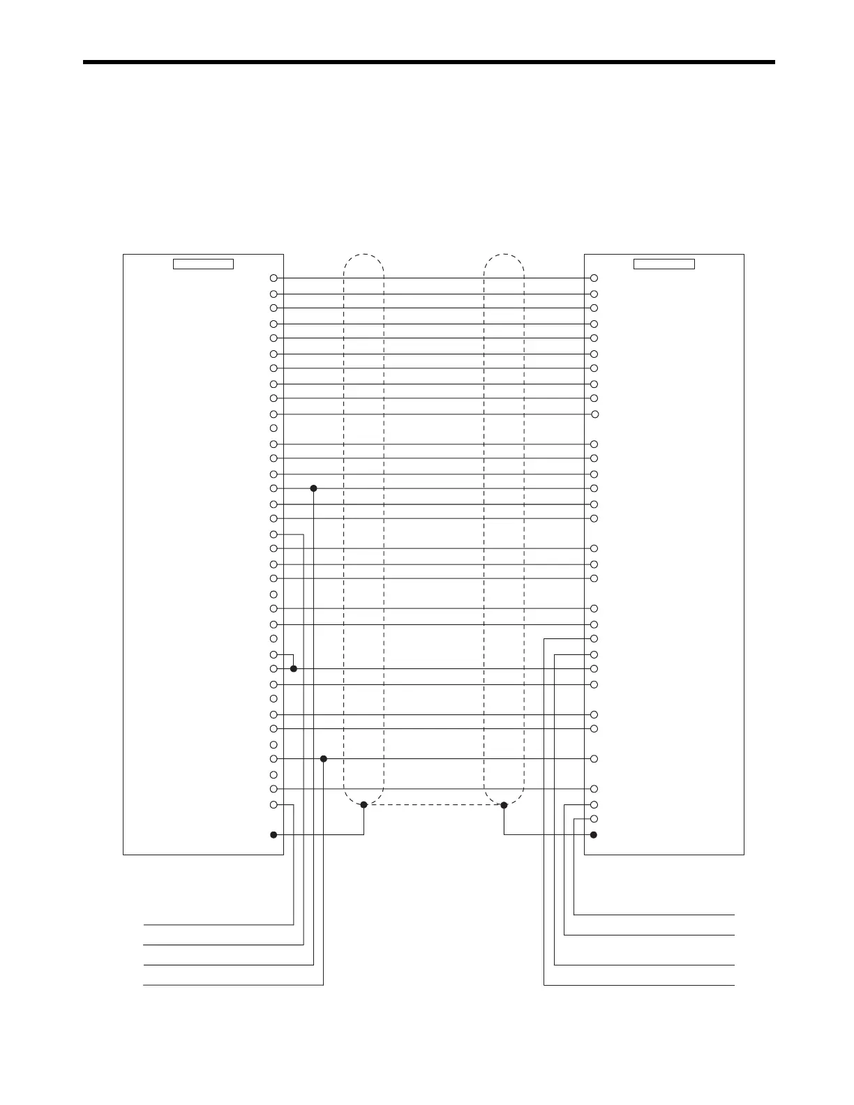
[ h ] SERVOPACK Connection Cables for SGDB-
■
Model
No standard cable is available. Prepare a cable referring to the following cable connections diagram.
■
Cable Connections Diagram
SGDB
AO_0 (NREF)
PAL
PCL
AI_0 (
VTG)
0V
(For 24 V)
DO_2 (PCON)
DO_3
+24V
DI_2 (
ZERO/HOME LS)
SG
PA
PC
SG
AO_1 (
TREF)
0V
DO_4
DI_3 (
P-OT)
DI_0 (
SVALM)
SEN (
5V)
DO_5
(SEN for VS866)
−
PBL
AI-GND
0V
DO_1 (
ALMRST)
+24V
DI_5 (
EXT/DEC)
SG
AI_1 (
TMON)
PB
SG
AO-GND
0V
DO_0 (
SV ON)
DI_4 (
N-OT)
DI_1 (
SRDY)
1
2
3
4
5
6
7
8
9
10
11
12
13
14
15
16
17
18
19
20
21
22
23
24
25
26
27
28
29
30
31
32
33
34
35
36
SG2
V-REF5
PA33
/PA34
PC19
/PC20
SG6
T-REF9
ALM-32
CN1/CN2
/P-CON 41
CN1
SVA-01
P-OT42
+24V IN47
ALM+31
ZERO/HOME LS input
P-OT input
N-OT input
EXT/DEC input
TGON- (/BRK-)28
SG10
SEN4
BAT-22
BAT+21
PB35
/PB36
SG1
TGON+ (/BRK+)27
/ALM-RST44
/S-ON40
N-OT43
Brake interlock output (+)
ABS encoder battery (0 V)
ABS encoder battery (3.6 V)
Hood FG FG
Hood
VTG-M17
TRQ-M16
Brake interlock output (−)
/S-RDY+29
/P-CL (User-set)45
/N-CL
(User-set)46
/S-RDY-30
(For 24 V)
(For 24 V)
(For 24 V)
(Torque monitor
output)
(Control
mode switch)
(Speed monitor
output)
WWW.NNC.IR