Fieldbus PCI-Card
3.3 I/O map
Depending on the application of the system, the number of userdefinable I/O points will vary. The
robot controller I/O’s follows a basic octal numbering system, i.e. each input or output group will occur
in a grouping of eight.
• The NX100 system has the capability of supporting 1024 input and 1024 output signals.
• The DX100 system has the capability of supporting 2048 input and 2048 output signals.
3.3.1 Fieldbus input data map
The data received from the PCI fieldbus card appears in the robot controller memory map according
to the tables below. The base address in the robot controller where the data will appear depends on
the installation. In the examples below the PCI card inputs are represented from address 20060
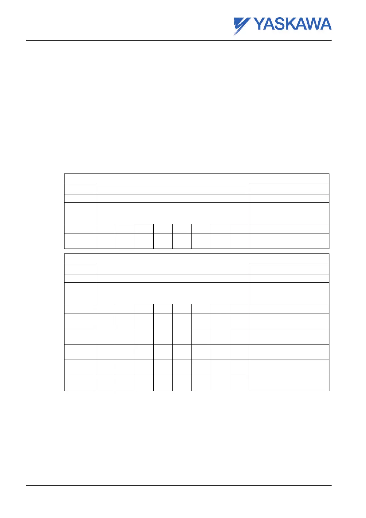
Memory map when the I/O size is set to a total of 24 input bits (16 fieldbus input bits)
Address Contents
Description
MSB LSB
20060 Module and network status Status information. See
section3.4 Fieldbus status
byte
20070 b7 b6 b5 b4 b3 b2 b1 b0 Fieldbus input byte 1 (b0 - b7)
20080 b15 b14 b13 b12 b11 b10 b9 b8 Fieldbus input byte 2 (b8 -
b15)
Memory map when the I/O size is set to a total of 56 input bits (48 fieldbus input bits)
Address Contents
Description
MSB LSB
20060 Module and network status Status information. See
section3.4 Fieldbus status
byte
20070 b7 b6 b5 b4 b3 b2 b1 b0 Fieldbus input byte 1 (b0 - b7)
20080 b15 b14 b13 b12 b11 b10 b9 b8 Fieldbus input byte 2 (b8 -
b15)
20090 b23 b22 b21 b20 b19 b18 b17 b16 Fieldbus input byte 3 (b16 -
b23)
20100 b31 b30 b29 b28 b27 b26 b25 b24 Fieldbus input byte 4 (b24 -
b31)
20110 b39 b38 b37 b36 b35 b34 b33 b32 Fieldbus input byte 5 (b32 -
b39)
20120 b48 b47 b46 b45 b44 b43 b41 b40 Fieldbus input byte 6 (b40 -
b48)
3.3.2 Fieldbus output data map
The data transferred from the robot controller to the PCI fieldbus card appears in the robot controller
memory map according the table below. The base address in the robot controller where the data will
appear depends on the installation. In the examples below the PCI card inputs are represented from
address 30060.
Page 20 Reg.No. ME00107EN-02

 Loading...


