Manual I/O allocation (FD 134)
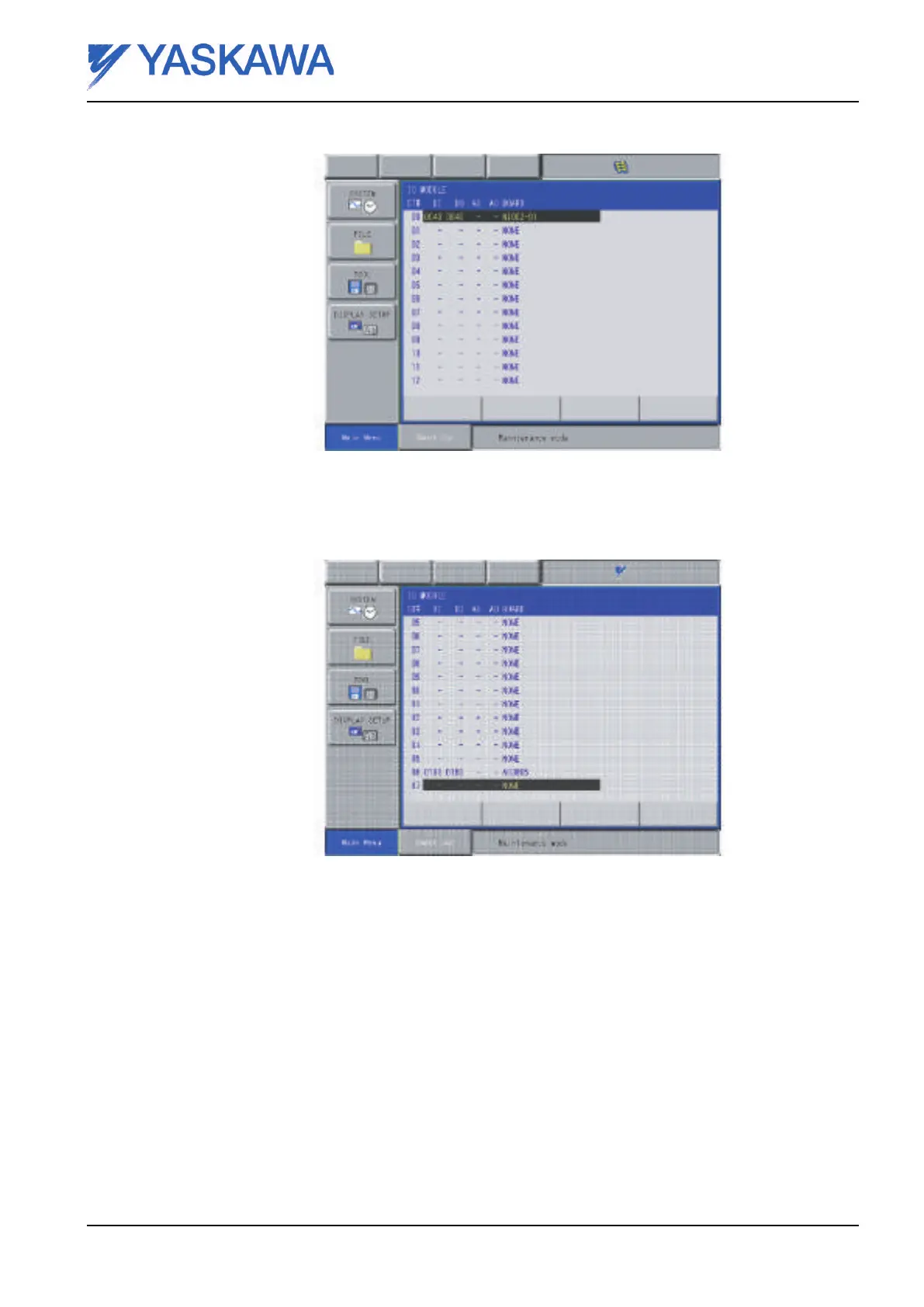
Fig. 14 IO MODULE settings
15. In the IO MODULE, press [ENTER]. The card in CPU option 1 will allways be placed as number
16 (card in CPU option 2 as No.17). The amount of desired Inputs and Outputs (I/O’s) are shown
(in DeviceNet Master ex. above 20 bytes x 8 bits + 8 status bits = 168 bits).
Fig. 15 PCI card (AB3602 Profibus M)
16. The last position will automatically be marked, press [ENTER] again.
17. The question “MODIFY” appears. Select YES.
3.2 Manual I/O allocation (FD 134)
The installed PCI-cards are given specific areas by default. But from generation DX100 it is possible
to allocate certain areas. As an option this possibility can be enabled. The procedure for this function
is located in a separate instruction for External I/O signal allocation function.
Reg.No. ME00107EN-02 Page 19

 Loading...


