DeviceNet network setup
No: Indication State
Meaning
4
Operation mode
-
No power or not initialized
Green, flashing Idle mode
Green Run mode
5 Network status
Off No power, not initialized or no
connection established
Green, flashing Online, no connection established
Green Online, at least one connection
established
Red, flashing Minor fault; at least one connection
has a minor fault
Red Critical link failure
6 Module status
Off No power or not initialized
Green Module status OK
Red, flashing Minor fault
Red Major fault
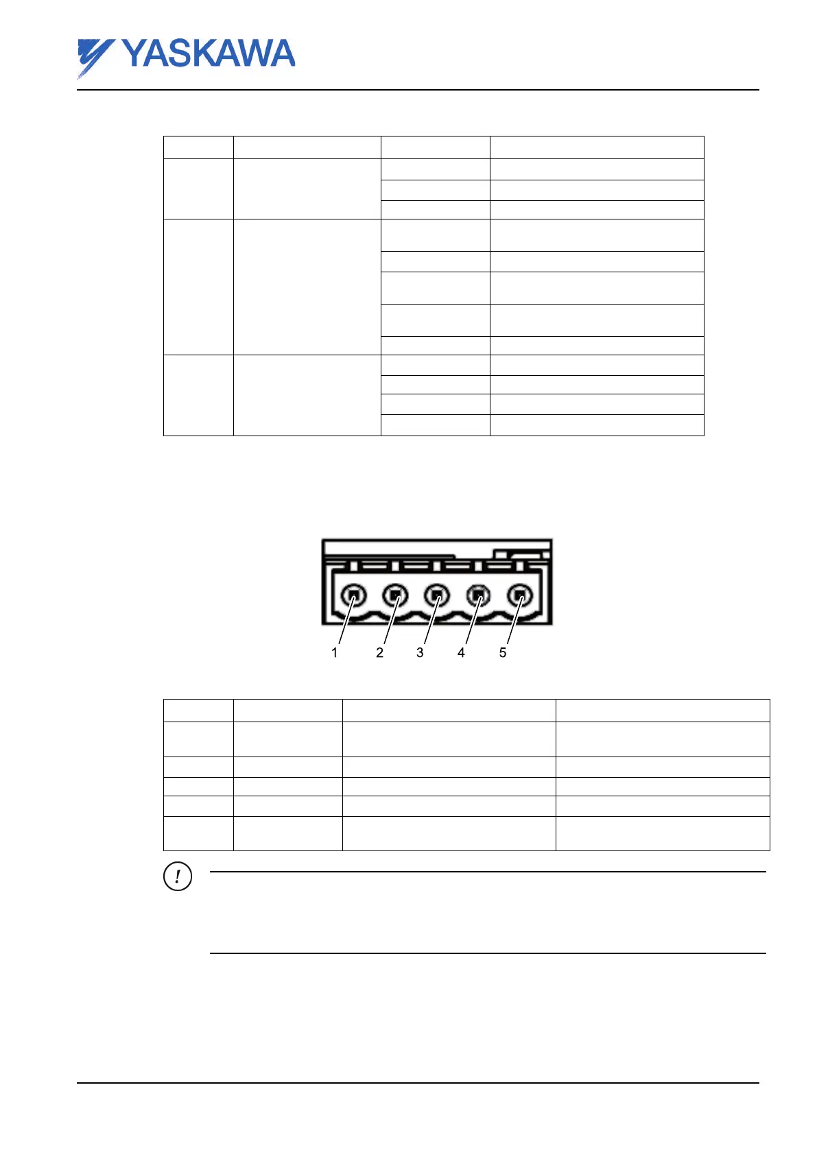
8.2.2 Connectors
Fieldbus interface
Fig. 25 Male Connector DeviceNet
No:
Signal
Decription
Note
1
V- Negative supply voltage The module requires 24VDC bus
power
2
CAN_L CAN_L bus line
3 shield Cable shield
4
CAN_H CAN_H bus line
5
V+ Positive supply voltage The module requires 24VDC bus
power
The layout in Fig. 25 Male Connector DeviceNet is for a male connector. Female connectors
are in the opposite order.
8.3 DeviceNet network setup
To be able to setup the DeviceNet fieldbus network, the AnyBus NetTool for DeviceNet is
recommended to use.
Reg.No. ME00107EN-02 Page 37

 Loading...


