7 Operation
7.4.2 Using the Electronic Gear Function
7-16
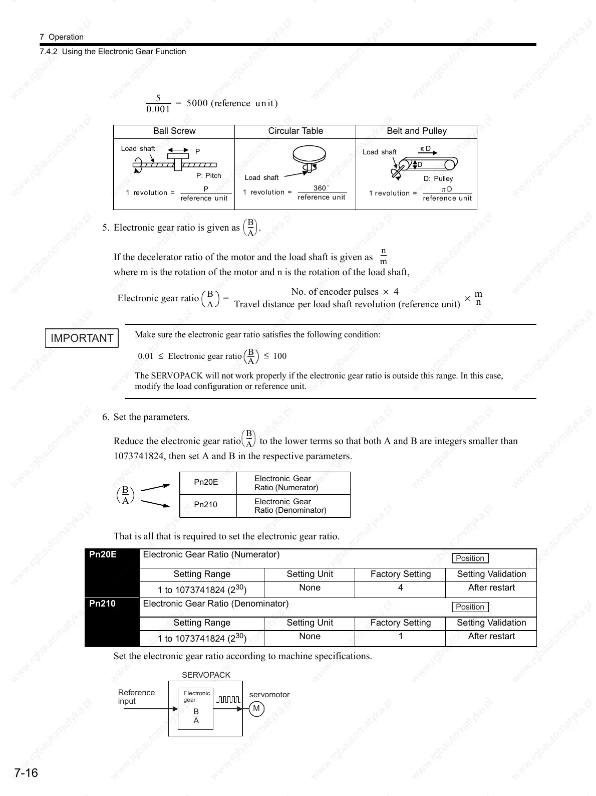
5. Electronic gear ratio is given as .
If the decelerator ratio of the motor and the load shaft is given as
where m is the rotation of the motor and n is the rotation of the load shaft,
Make sure the electronic gear ratio satisfies the following condition:
The SERVOPACK will not work properly if the electronic gear ratio is outside this range. In this case,
modify the load configuration or reference unit.
6. Set the parameters.
Reduce the electronic gear ratio to the lower terms so that both A and B are integers smaller than
1073741824, then set A and B in the respective parameters.
That is all that is required to set the electronic gear ratio.
Set the electronic gear ratio according to machine specifications.
Ball Screw Circular Table Belt and Pulley
5
0.001
=5000(referenceunit)
Load shaft
P: Pitch
P
1revolution=
P
reference unit
Load shaft
1revolution=
360˚
reference unit
D: Pulley
D
π D
Load shaft
1revolution =
π D
reference unit
B
A
----
n
m
----
Electronic gear ratio
B
A
=
No. of encoder pulses × 4
Travel distance per load shaft revolution (reference unit)
×
m
n
IMPORTANT
0.01 ≤ Electronic gear ratio
B
A
100
≤
B
A
----
B
A
Pn20E
Pn210
Electronic Gear
Ratio (Numerator)
Electronic Gear
Ratio (Denominator)
Pn20E Electronic Gear Ratio (Numerator)
Setting Range Setting Unit Factory Setting Setting Validation
1 to 1073741824 (2
30
)
None 4 After restart
Pn210 Electronic Gear Ratio (Denominator)
Setting Range Setting Unit Factory Setting Setting Validation
1 to 1073741824 (2
30
)
None 1 After restart
Position
Position
M
Reference
input
SERVOPACK
servomotor
Electronic
gear
B
A
 Loading...

