7.4 Settings According to Host Controller
7-17
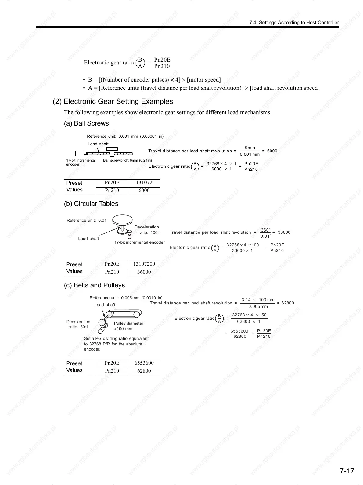
• B = [(Number of encoder pulses) × 4] × [motor speed]
• A = [Reference units (travel distance per load shaft revolution)] × [load shaft revolution speed]
(2) Electronic Gear Setting Examples
The following examples show electronic gear settings for different load mechanisms.
(a) Ball Screws
(b) Circular Tables
(c) Belts and Pulleys
Electronic gear ratio
B
A
=
Pn20E
Pn210
Preset
Values
Pn20E 131072
Pn210 6000
Ball screw pitch: 6mm (0.24in)17-bit incremental
encoder
Load shaft
Reference unit: 0.001 mm (0.00004 in)
Travel distance per load shaft revolution =
6mm
0.001 mm
= 6000
Electronic gear ratio
B
A
=
32768
×
4 × 1
6000 × 1
=
Pn20E
Pn210
Preset
Values
Pn20E 13107200
Pn210 36000
17-bit incremental encoder
Load shaft
Travel distance per load shaft revolut ion =
360˚
0.01˚
= 36000
Electonic gear ratio
B
A
=
32768 × 4 × 100
36000 × 1
=
Pn20E
Pn210
Reference unit: 0.01°
Deceleration
ratio: 100:1
Preset
Values
Pn20E 6553600
Pn210 62800
Load shaft
Travel distance per load shaft revolution =
3.14 × 100 mm
0.005 mm
= 62800
Electronic gear ratio
B
A
=
32768 × 4 × 50
62800 × 1
Pn20E
Pn210
Deceleration
ratio: 50:1
Reference unit: 0.005mm (0.0010 in)
Pulley diameter:
φ
100 mm
Set a PG dividing ratio equivalent
to 32768 P/R for the absolute
encoder.
==
6553600
62800
 Loading...

