6.4 Others
6-23
6
(b) Three-phase 200 V
SGDM-05AD (SGDM-05ADA) to -1EADA (Three-phase 200 VAC, 500 W to 15.0 kW)
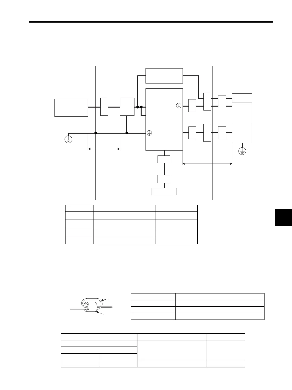
(2) Cable Core and Cable Clamp
(a) Attaching the Ferrite Core
The diagram shows two turns in the cable.
The table shows the cable and the position where the ferrite core is attached.
(b) Recommended Ferrite-core
Symbol Cable Name Specifications
c
I/O Signals cable Shield cable
d
Servomotor cable Shield cable
e
Encoder cable Shield cable
f
AC Line cable Shield cable
U, V, W
L1, L2, L3
L1C, L2C
CN2
CN1
PE
PE
Ground Plate / Shield Box
Core
Approx. 5 m (16.4 ft)
Core
Core
Core
SERVOPACK
Brake power
supply
Core
Core
Host controller
Noise
filter
Clamp
Approx. 2 m (6.56 ft)
Power Supply
Three-phase
200 VAC
Clamp
Clamp
Brake
Servo-
motor
Encoder
Cable Name Mounting Position of the Core
I/O signals cable Near the host controller and the SERVOPACK.
Motor cable Near the SERVOPACK and the servomotor.
Encoder cable Near the SERVOPACK and the servomotor.
Cable Name Ferrite Core Model Manufacturer
I/O signals cable
ESD-SR-25 Tokin. Corp.Encoder cable
Motor cable
400 W or less
500 W or more
PC40T96
× 20 × 70
TDK
Cable
Ferrite core
Artisan Technology Group - Quality Instrumentation ... Guaranteed | (888) 88-SOURCE | www.artisantg.com

 Loading...


