5-8
IM 701510-01E
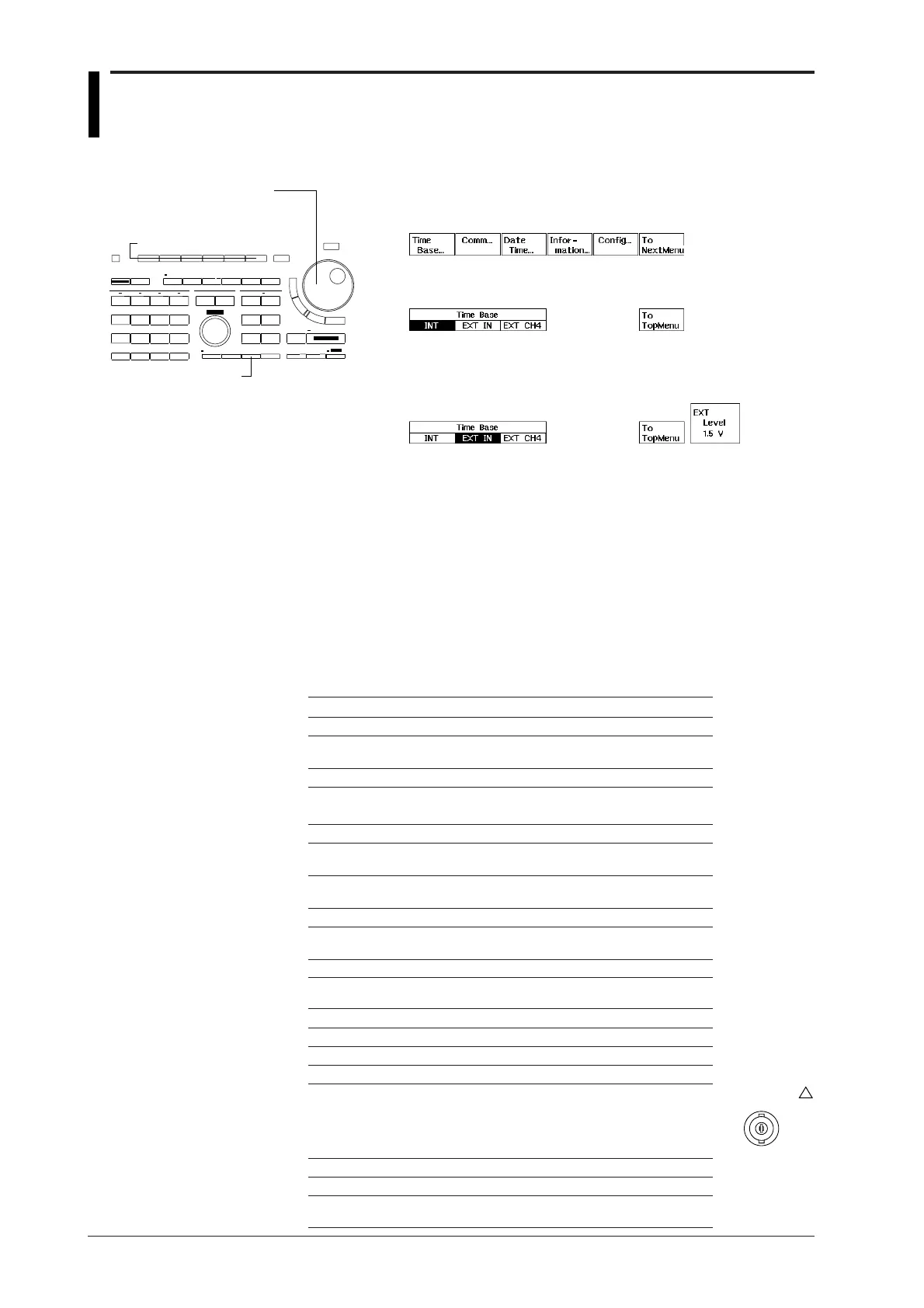
5.7 Selecting the Timebase
1. Press the MISC key to display the MISC menu.
2. Press the “Time Base...” soft key to display the timebase setting
menu.
3. Select the required timebase by pressing the corresponding soft key.
“EXT CH4” menu is available on DL1540/DL1540L.
4. In case you selected “EXT IN” or “EXT CH4”, use the rotary knob to
set the required threshold level. “EXT CH4” menu is available on
DL1540/DL1540L.
Explanation
Selectable Timebases
Timebase can be selected from the following three types.
INT Internal clock signal
EXT IN Clock signal input to the EXT TRIG IN/EXT CLOCK IN terminal
EXT CH4 Clock signal input to the CH4 input terminal
(Available on DL1540/DL1540L)
When “EXT IN” is selected
Input a clock signal to the EXT TRIG IN/EXT CLOCK IN terminal on the rear panel (for
DL1520/DL1520L, EXT TRIG terminal on the front panel). The clock signal must conform
to the specifications given below.
• For DL1520/DL1520L
Item Specifications
Connector type BNC
Maximum input voltage 250 V(DC+ACpeak) or 177 Vrms, when the
frequency is 1 kHz or below, (CAT I and II)
Input band DC to 100 MHz
Fequency range of external 40 Hz to 80 MHz
clock
Input range 2 ranges (±10 V and ±1 V)
Input level range ±10 V range: –10 V to + 10 V in steps of 40 mV
(Probe attenuation ratio 1:1) ±1 V range: –1 V to + 1 V in steps of 4 mV
Input sensitivity 2 Vp-p (±10V range)
(Probe attenuation ratio 1:1) 200 mVp-p (±1V range)
Input coupling AC/DC
HF rejection Bandwidth limit (approx. DC to 15 kHz)
for the input signal can be turned ON/OFF.
Input impedance Approx. 1 MΩ (same as section 16.1)
• For DL1540/DL1540L
Item Specifications
Connector type BNC
Maximum input voltage ±6 V
Frequency range 40 Hz to 15 MHz
Input level TTL/CMOS level recommended
0.3 Vp-p or greater when measured
at the end of the connector
±0.15 V or greater relative to the
threshold level
Input impedance Approx. 1 MΩ
Threshold level 1.5 V or 0.15 V
Minimum pulse width 25 ns or more for both
High and Low levels
Keys and Procedure
MISC key
Rotary knob
Soft keys
Input terminal
Example
(DL1540/DL1540L)
EXT CLOCK IN
EXT TRIG IN
±6V MAX 1MΩ
!

 Loading...


