IM 701510-01E
14-1
Other Operations
14
14.1 Using a Trigger Output Signal (for DL1540/
DL1540L)
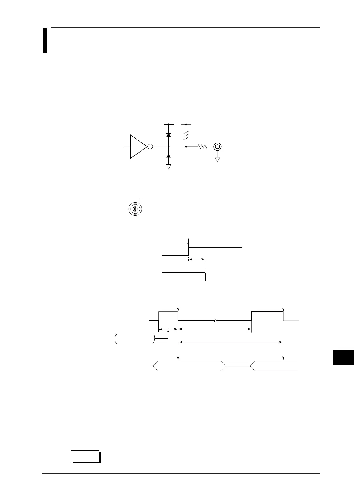
Trigger Output Circuit
Output level : TTL
Output logic : Negative (trailing edge)
Output delay time : 150 ns max.
Output hold time : 2 µs min. for low level, 2 µs min. for high level
Output Circuit
51 Ω
LS06
2.2 kΩ
5 V 5 V
Trigger Output Terminal
The TRIG OUT terminal is situated on the rear panel.
TRIG OUT
(TTL )
Output timing
A trigger is activated.
150ns max
H
L
Trigger output
Trigger signal
Hold Time for Low and High Level
H
L
Trigger output
(Post-trigger time + Internal process time)
A trigger is activated.
A trigger is activated.
Pre-trigger
(Repeat interval for trigger output)
Trigger Trigger
Post-triggerPost-trigger Pre-trigger
Acquisition
Pre-trigger +
Internal process time
*2
*3
*1
*1: Duration during which the trigger output level is HIGH
Consists of the pre-trigger time and internal process time. (2 µs or longer)
*2: Duration during which the trigger output level is LOW
Consists of the post-trigger time and internal process time. (2 µs or longer)
*3: (Repeat interval)
The minimum repeat interval for trigger output differs according to the selected mode.
Real-time sampling mode : Approx. 17 ms
Equivalent sampling mode : Approx. 10 µs
Single (N) mode : Approx. 300 µs
CAUTION
Never apply an external voltage to the TRIG OUT terminal, as damage to the
instrument may result.

 Loading...


