9-13
IM 701510-01E
Performing a GO/NO-GO Action
9
9.3 Using the GO/NO-GO Signal Output
Function(for DL1540/DL1540L)
Output Signal
NO-GO OUT signal
The output signal level (TTL level) changes from high to low (L) temporarily when a “NO-
GO” determination is made.
GO OUT signal
The output signal level (TTL level) changes from high to low (L) temporarily when a “GO”
determination is made.
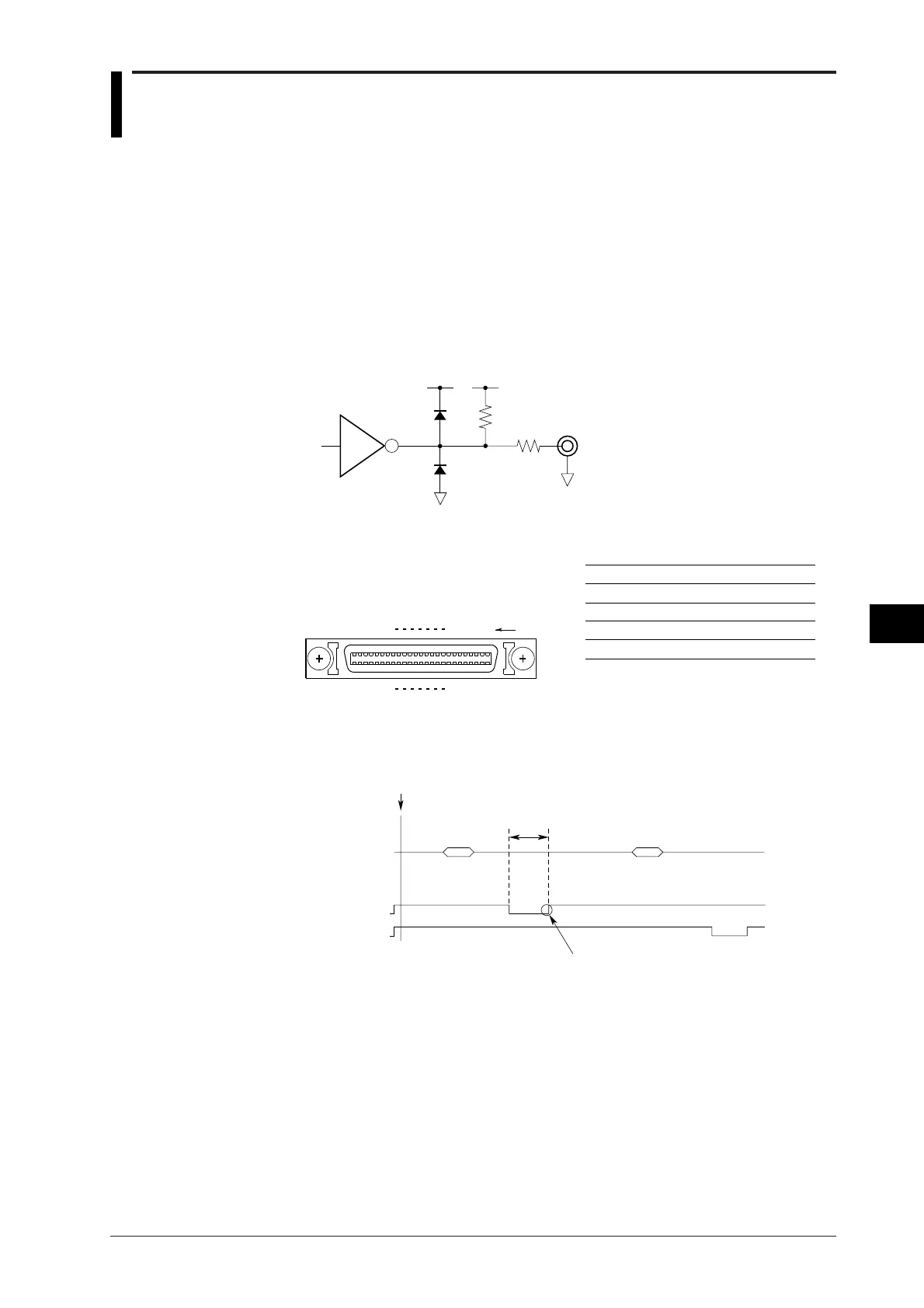
Signal output circuit diagram
51 Ω
LS06
2.2 kΩ
5 V 5 V
Output Connector
125
2650
2
27
3
28
24
49
23
48
Pin configuration
Pin No.
Pin No.
1
2
26
27
Signal name
NO-GO OUT
GND
GO OUT
GND
OPTION
* Only use pin No. 1, 2, 26, and 27.
Other pins are used for other
communication
ur
oses.
Output Timing
Output timing
EXEC
10ms
or more
Acquisition Acquisition
Determination Determination
Result Result
NOGO OUT
GO OUT
Remains 'Low' until the system
is ready for the next judgement
(or for longer if the data is to
be output to the built-in printer
or to a floppy disk).

 Loading...


