3-3
IM 701510-01E
Before Starting Observation and Measurement of Waveforms
3
3.3 Connecting the SCSI cable (for DL1520L with
suffix code -C4)
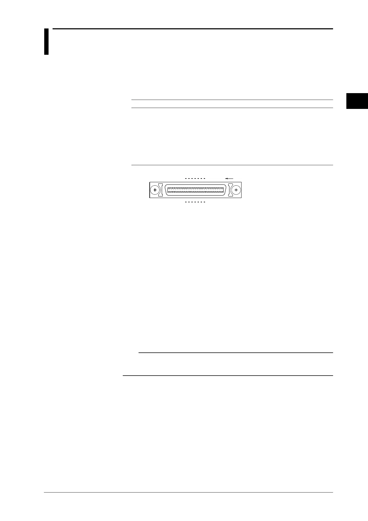
Name, position and pin cofigurationo of the SCSI cable connector
• Name : OPTION
• Position : Real panel of DL1520L
• Pin configuration
Pin No. Signal name Pin No. Signal name Pin No. Signal name
1 to 12 GND 32 -DB6 43 -BSY
13 NC 33 -DB7 44 -ACK
14 to 25 GND 34 -DBP 45 -RST
26 -DB0 35 to 37 GND 46 -MSG
27 -DB1 38 TERMPWR 47 -SEL
28 -DB2 39,40 GND 48 -C/D
29 -DB3 41 -ATN 49 -REQ
30 -DB4 42 GND 50 -I/O
31 -DB5
125
2650
2
27
3
28
24
49
23
48
(Rear panel)
Pin No.
OPTION
Other necessary equipment
SCSI Device
SCSI devices which can send and receive data over SCSI and can set the ID number to "5"
can be connected the instrument. There are exceptions as in the case when the media used
on the SCSI device is formatted with another equipment such as a PC, or the pin
configuration of the connector is different. Refer to section 16.7, for the SCSI specification.
Also, for information on general precautions in using the SCSI device, refer to the
instruction manual for that device.
SCSI cable
SCSI cables should have the connector shape and pin configuration which match the
"OPTION" connector on the rear panel of the DL1520L (refer to the figure above). They
should be less than 3 m long with a characteristic impedance between 90 and 132 Ω. Also,
attach a ferrite core (TDK:ZCAT2035-0930A) on each end of the cable.
Terminator
Some SCSI devices require terminators. Follow the instruction manual for the SCSI device.
Note
DL1540/DL1540L with software (ROM) version 1.20 or later can save/load data from the SCSI device
through the SCSI interface unit 700930 (sold separately). For details, refer to the instruction manual for
the SCSI interface unit 700930, IM700930-01E.

 Loading...


