8-2
IM 701510-01E
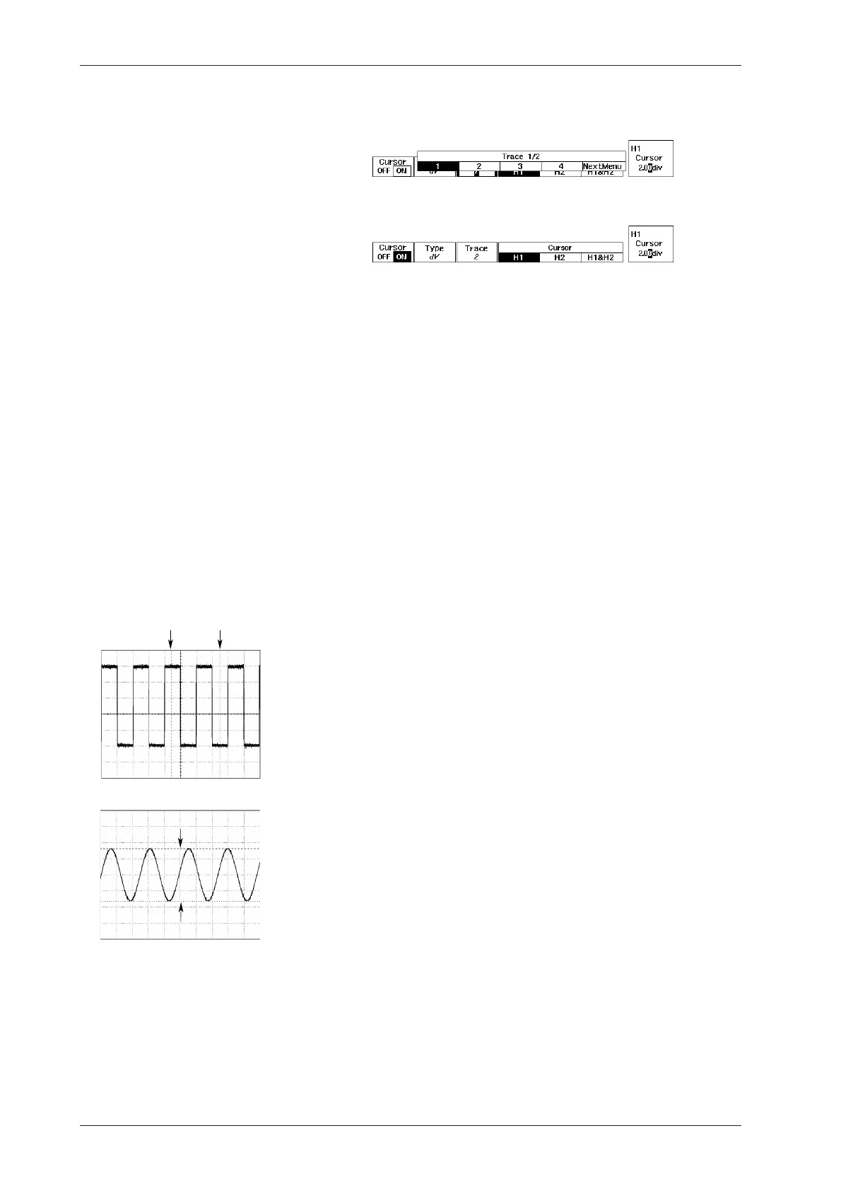
6. Press the soft key corresponding to the trace you want to measure.
For DL1520/DL1520L, menus such as “1”, “2”, “MATH”, “LOAD1” and
“LOAD2” are displayed instead of the trace selection menu shown below.
7. After having pressed any of the “H1”, “H2” or “H1&H2” soft keys,
use the rotary knob to adjust the position of the cursor.
Explanation
Waveforms which cannot be measured using cursors
The following waveforms are excluded from measurements using cursors.
• Snapshot waveform;
• Accumulated waveforms other than the most recent one;
•Waveforms other than those which are specified (by Display Number) and displayed (by
Display Trace) using the sequential store or history memory function.
Selecting the measurement waveform: Trace
When “V-T” or “dV” has been selected at the type selection menu, the following can be
selected at the trace menu. The menu is divided into two menus, which can be reached using
the “PrevMenu” and “NextMenu” soft keys.
1-4 Measurements will only be performed on the selected trace;
LOAD1-4 Measurements will only be performed on the selected loaded waveform;
ALL (in case of “V-T” only) Measurements will be performed on all traces and
loaded waveforms.
* For DL1520/DL1520L, a selection menu is used to select one of “1”, “2”, “MATH”, “LOAD1”,
“LOAD2” and “ALL”. “ALL” is displayed only when “V-T” is selected as the target to be
measured.
Measurement items
The following items can be measured.
• Using vertical cursors to measure time difference/ frequency/ voltage/
voltage difference : V-T
In all cases excluding “ALL”
T1 Time difference between position of cursor T1 and trigger position
T2 Time difference between position of cursor T2 and trigger position
DT Time difference between positions of cursors T1 and T2
1/DT Reciprocal of DT (frequency)
V1(X) Voltage at the position where the waveform intersects cursor T1
V2(X) Voltage at the position where the waveform intersects cursor T2
DV(X) V2-V1
(X) indicates the waveform of measurement, e.g. LOAD1 is shown as (L1)
In the case of “ALL”
T1 Time difference between position of cursor T1 and trigger position*
T2 Time difference between position of cursor T2 and trigger position*
DT Time difference between positions of cursors T1 and T2
1/DT Reciprocal of DT (frequency)
V1(X) Voltage at the position where all waveforms intersect cursor T1. The waveform
of measurement is indicated between brackets.
* In case of roll mode, this is not the trigger position, but the center of the acquisition memory
record length. This position is shown at the 0div in the figure on page 1-7.
• Using vertical cursors to only measure time difference : dT
DT Time difference between positions of cursors T1 and T2
1/DT Reciprocal of DT (frequency), for DL1520/DL1520L
• Using horizontal cursors to only measure voltage difference : dV
DV(X) V2-V1; where V2 is the position where the waveform intersects cursor H2, and
V1 is the position where the waveform intersects cursor H1.
8.1 Measuring a V-T Waveform using Cursors
T1 cursor T2 cursor
H2 cursor
H1 cursor

 Loading...


