1-1
IM DLM3054-01EN
1 Vertical Axis (Analog Signal)
You can configure the vertical scale, vertical position, input coupling, probe attenuation, linear scaling, and
bandwidth limit settings of the CH1 through CH4 input signals.
If you are using a probe that is compatible with this instrument’s probe interface, the instrument automatically
configures the input impedance (50 Ω or 1 MΩ) and the probe attenuation.
Turning the Display On and Off (Display)
Select whether show or hide each channel’s input signal waveform.
• ON: The waveform is shown.
• OFF: The waveform is hidden.
Vertical Scale (SCALE knob)
The vertical scale is used to adjust the displayed waveform amplitude so that you can easily view signals. Set
the vertical scale by voltage per grid square (V/div) or current per grid square (A/div) on the screen.
Set the vertical scale using the SCALE knob for each channel.
The SCALE knob is shared between channels. Press the CH1 to CH4 keys to select the channel that you want
to set the vertical scale for. The LED between the SCALE and POSITION knobs illuminates in the color assigned
to the selected channel (yellow, green, magenta, or cyan).
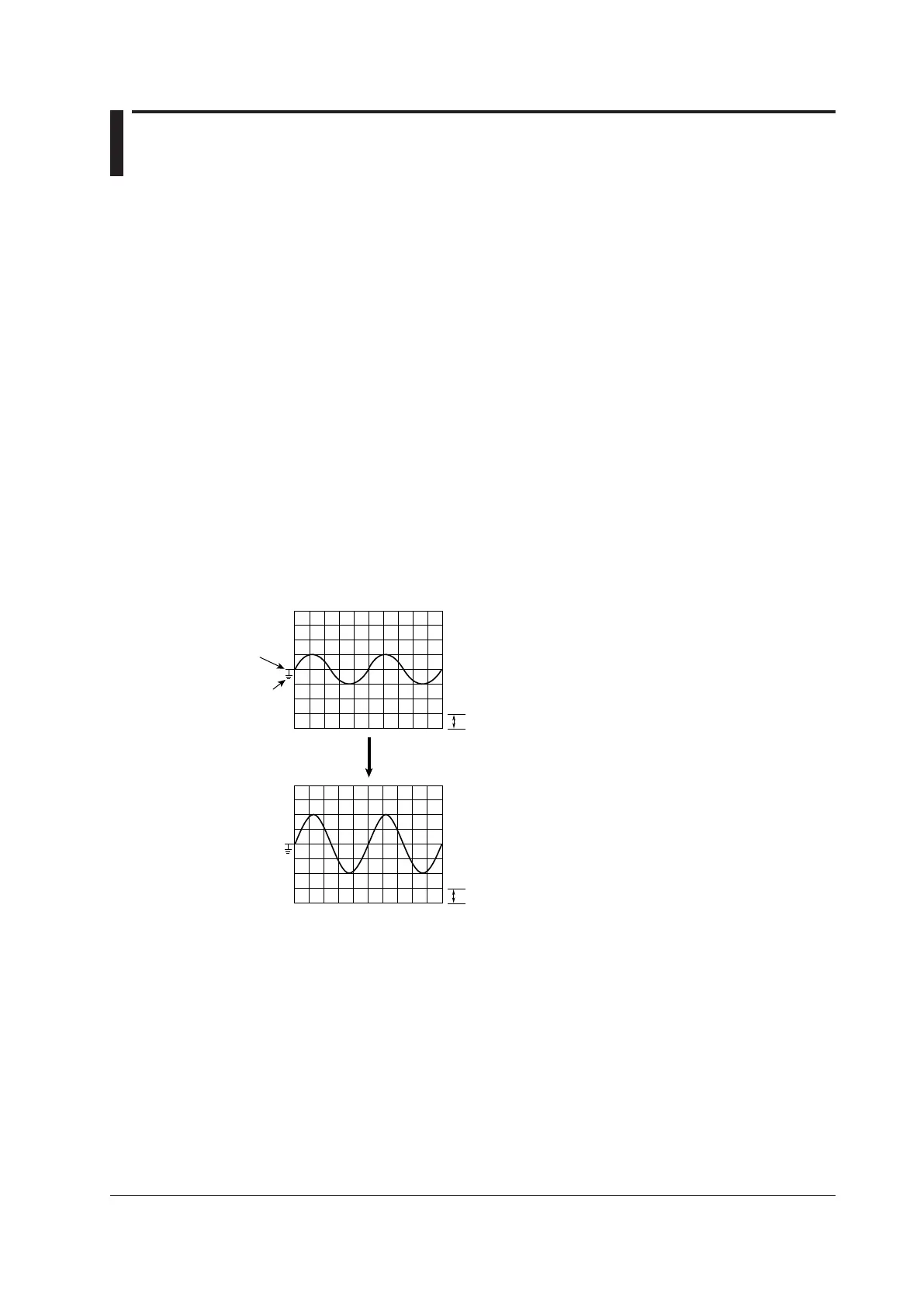
Setup Example
1 div = 1.00 V
If 1.00 V/div is changed
to 0.500 V/div
Vertical position
mark
Ground level
mark
 Loading...


