17-2
IM DLM3054-01EN
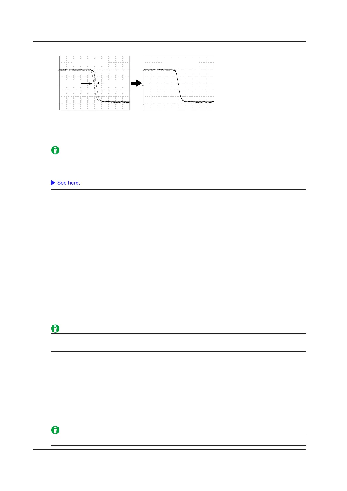
Example of Deskewing
Before deskewing
After deskewing
Voltage
waveform
Current
waveform
Switching Loss Analysis (SW Loss)
You can measure the device’s total loss (power loss) and switching loss (power loss during switching).
If you select SW Loss, you can calculate statistics and display power waveforms and measured values.
You can display a total of up to 20 switching loss measurement items and automatically measured waveform
parameter items. If measured switching loss values are not displayed, reduce the number of automatically
measured waveform parameter items.
Probe Setup (ProbeSetup)
Selecting Channels (Input Channels)
Select CH1 and CH2 or CH3 and CH4. You cannot change these pairs.
To measure power supply analysis items, apply the voltage signal to CH1 or CH3 and the current signal to CH2
or CH4.
Probe Attenuation Ratio and Voltage-to-Current Conversion Ratio (Probe CH1/CH2 or Probe CH3/CH4)
Select one of the probe attenuation ratios (CH1 or CH3) and one of the voltage-to-current conversion ratios (CH2
or CH4) listed below.
• CH1, CH3
0.001:1, 0.002:1, 0.005:1, 0.01:1, 0.02:1, 0.05:1, 0.1:1, 0.2:1, 0.5:1, 1:1, 2:1, 5:1, 10:1, 20:1, 50:1, 100:1,
200:1, 500:1, 1000:1, 2000:1
• CH2, CH4
0.001 A: 1 V, 0.002 A: 1 V, 0.005 A: 1 V, 0.01 A: 1 V, 0.02 A: 1 V, 0.05 A: 1 V, 0.1 A: 1 V, 0.2 A: 1 V, 0.5 A: 1 V,
1 A: 1 V, 2 A: 1 V, 5 A: 1 V, 10 A: 1 V, 20 A: 1 V, 50 A: 1 V, 100 A: 1 V, 200 A: 1 V, 500 A: 1 V, 1000 A: 1 V, 2000 A:
1 V
Changing the probe attenuation ratio or voltage-to-current conversion ratio here will change the same ratio in
the CH key probe settings.
Deskewing Manually (Deskew CH1/CH2 or Deskew CH3/CH4)
You can set values for deskewing the transfer time difference between signals on each channel.
Auto Deskew Reference Waveform (Ref Trace)
Sets the reference waveform for auto deskewing. The instrument deskews the input signals by using the
specified waveform as its reference.
Auto Deskewing (Auto Deskew)
Executes auto deskewing.
You can also manually deskew the input signals by using the jog shuttle.
17 Power Supply Analysis Feature (Power Analysis and Power Measurement, Option)
 Loading...


