1-3
IM DLM3054-01EN
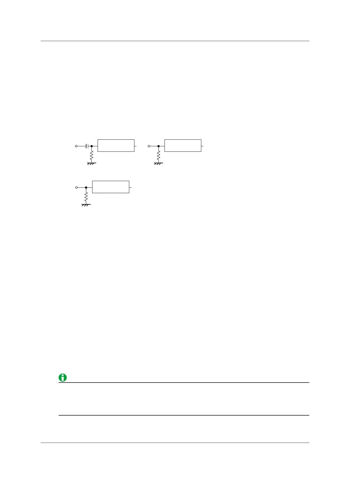
Input Coupling (Coupling)
You can change the coupling used to input analog signals into the vertical (voltage) control circuit.
Select one of the following input coupling options.
AC
Displays only the AC component of the input signal. The input impedance is 1 MΩ.
DC
Displays both the AC and DC components of the input signal. The input impedance is 1 MΩ.
DC50
Displays both the AC and DC components of the input signal. The input impedance is 50 Ω. Pay attention
because the maximum input voltage (current) is small.
Vertical control
circuit
Input
terminal
1 MΩ
Vertical control
circuit
Input
terminal
50 Ω
Ω
Vertical control
circuit
Input
terminal
1 MΩ
Probe Attenuation (Probe)
When using a probe, the instrument’s attenuation ratio setting must be aligned with the probe attenuation so
that the voltage (current) and scale values are displayed correctly. Set the attenuation ratio to match the probe
attenuation.
Probe Type (Type)
Select the type of probe to set the attenuation ratio of.
• Voltage: Voltage probe
• Current: Current probe
Attenuation Ratio (Attenuation)
Select the attenuation ratio from the following.
Voltage probe
0.001: 1, 0.002: 1, 0.005: 1, 0.01: 1, 0.02: 1, 0.05: 1, 0.1: 1, 0.2: 1, 0.5: 1, 1: 1, 2: 1, 5: 1, 10: 1, 20: 1, 50: 1, 100:
1, 200: 1, 500: 1, 1000: 1, 2000: 1
Current probe
0.001 A: 1 V, 0.002 A: 1 V, 0.005 A: 1 V, 0.01 A: 1 V, 0.02 A: 1 V, 0.05 A: 1 V, 0.1 A: 1 V, 0.2 A: 1 V, 0.5 A: 1 V, 1 A:
1 V, 2 A: 1 V, 5 A: 1 V, 10 A: 1 V, 20 A: 1 V, 50 A: 1 V, 100 A: 1 V, 200 A: 1 V, 500 A: 1 V, 1000 A: 1 V, 2000 A: 1 V
Using a probe has the following advantages.
• Prevents the disturbance of the voltage and current of the circuit being measured.
• Allows signals to be applied with no distortion.
• Expands the voltage range that the instrument can measure.
1 Vertical Axis (Analog Signal)
 Loading...


