App-3
Appendix 2 User-Defined Computation
Digital Filter
Type
Type Bandwidth
FIR LowPass/HighPass/BandPass
IIR LowPass/HighPass/BandPass
Filter Order
See the following table for the filter orders.
2% 5% 10% 20% 30% (Cutoff*)
FIR LowPass 88 36 18 9 8
HighPass 159 65 33 17 13
IIR LowPass 4 4 4 3 2
HighPass 4 4 4 4 3
* The cutoff percentage is with respect to the sample rate.
Filter Response
Filter Pass-band Ripple Attenuation Slope Attenuation at the
Stop-band
Phase
FIR ±0.3 dB –40 dB at 1 oct (Lowpass), −40 dB Linear phase
−40 dB at −1 oct (Highpass)
-
Linear phase
IIR 0 dB –5 dB at 1/6 oct (Lowpass),
-
Non-linear phase
−20dB at−1oct(Highpass)
-
Non-linear phase
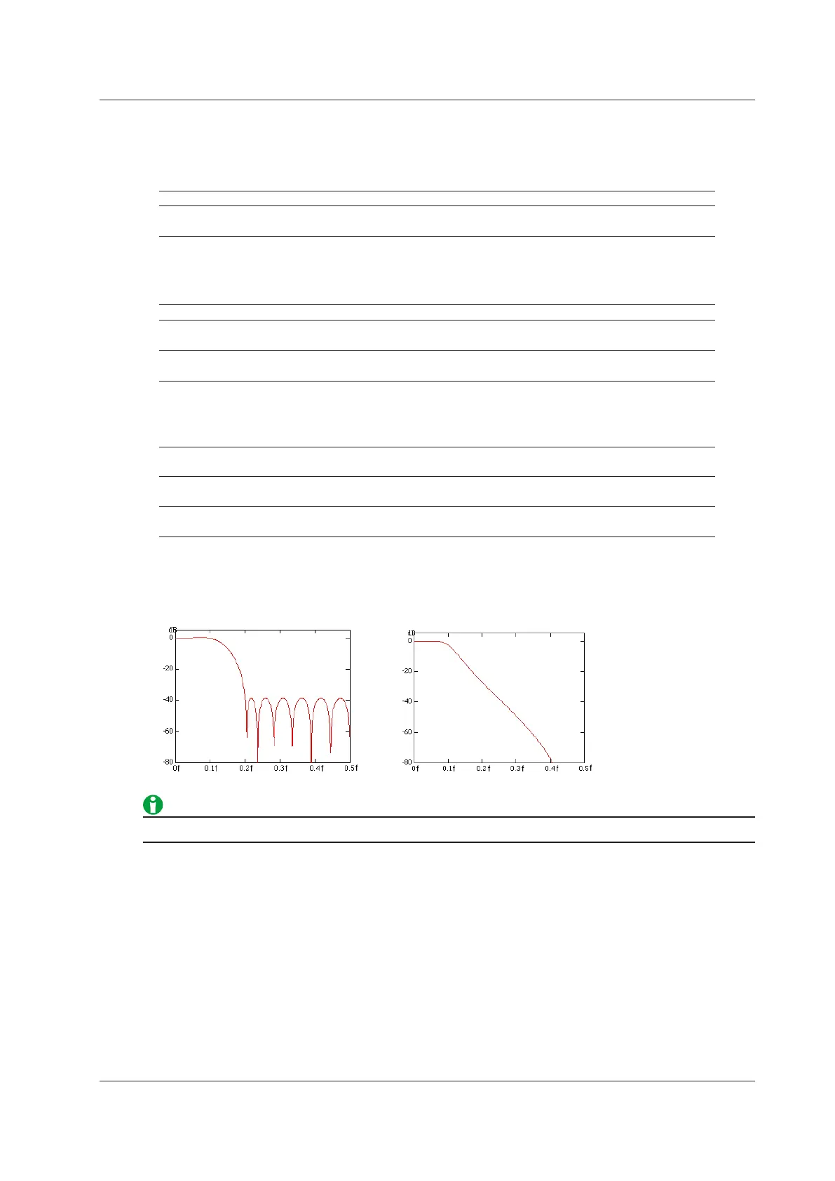
Examples of Filter Frequency Responses
f: Frequency (Hz)
FIR (low pass; 10% cutoff) IIR (low pass; 10% cutoff)
Computations take more time with higher filter orders.
Appendix
 Loading...


