4-24
IM DLM3054-01EN
I2C bus trigger
The I
2
C bus trigger is used to capture I
2
C bus signals.
An Inter Integrated Circuit (I
2
C) bus is a bi-directional bus for inter-IC communications.
SPI bus trigger
The SPI bus trigger is used to capture SPI bus signals.
A Serial Peripheral Interface (SPI) is a synchronous serial bus that is widely used for inter-IC communications
and data communications.
User-Defined Trigger
The user-defined trigger is used to capture user-defined serial bus signals.
The instrument synchronizes to the selected clock signal and detects a serial data pattern. You can specify up to
128 bits for the serial data pattern used for triggering. You can set the CS signal, which controls the period over
which the data source is checked, and the latch source, which specifies when patterns are compared.
Auto Setup
If you specify the serial bus type and the trigger source, the instrument can automatically configure the bit rate
and source level settings and then trigger based on those settings. The auto setup feature will not work properly
on some input signals. This feature is in the serial bus signal search feature.
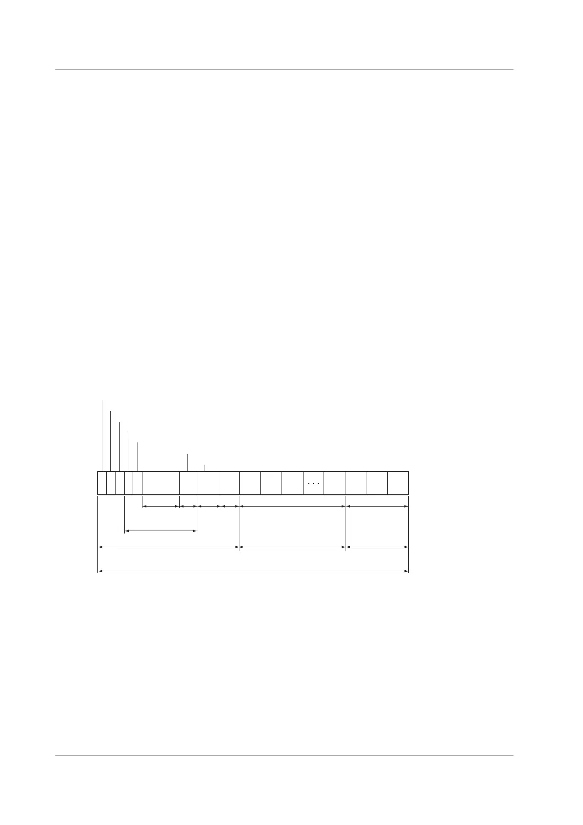
FlexRay Bus Trigger [ENHANCED, option]
The instrument triggers based on the trigger conditions of a particular frame or type of data in a FlexRay bus
signal.
Frame ID
Payload Length
Header
CRC
Cycle
Count
Data
0
Data
1
Data
2
Data
n
CRC CRC
CRC
Payload Preamble Indicator
Null Frame Indicator
Sync Frame Indicator
Startup Frame Indicator
1
1
1 1 1
11 Bits
7
Bits
11 Bits
6
Bits
0-254 Bytes
24 Bits
Header Segment
Payload Segment Trailer Segment
FlexRay Frame 5 + (0-254) + 3 bytes
Header CRC
Covered Area
Trigger Mode (Mode)
Select the FlexRay trigger mode from one of the settings below.
Frame Start: Triggers on the start of a frame
Error: Triggers on errors
ID/Data: Triggers on the AND of the ID bit pattern and Data pattern
ID OR: Triggers on the OR of multiple ID bit patterns
Frame Start
The instrument triggers on the start of FlexRay bus signal frames.
4 Triggering
 Loading...


