4-27
IM DLM3054-01EN
Data Pattern (Hex/Bin)
If the comparison condition is set to True or False, set the data pattern for the specified data size in
hexadecimal (Hex) or binary (Bin) notation.
If you specify X in the pattern, the condition is assumed to be met regardless of the corresponding bit
status.
If a binary pattern contains any Xs, the corresponding hexadecimal display will be “$.”
Size: 4
Data
0
Data
1
Data
3
Data
4
Data
2
Data
6
Data
7
Data
8
Data
5
XX XX
1 2
3 4
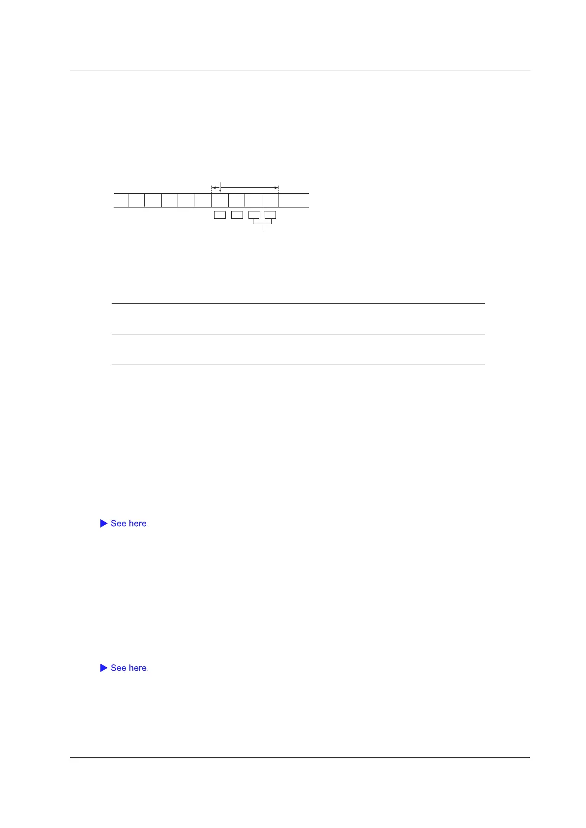
Example When the Comparison Start Position Is Set to 5 and
the Data Length Is Set to 4
Example when out of the four bytes, the lower 2 bytes is set to 1234
Position: 5
Reference Values (a and b)
If the comparison condition is set to Data = A, Data ≠ a, a ≤ Data, Data ≤ b, a ≤ Data ≤ b, or “Data < a or
b < Data,” set the reference values in decimal notation. You must set the byte order (Endian), sign (Sign),
and comparison range (MSB or LSB). The selectable ranges are as follows:
Unsigned
(Unsign)
0 to 9E+18
The selectable maximum value is limited by the data length and bit position, which
is determined by the Size and MSB/LSB settings, respectively.
Signed
(Sign)
−9E+18 to 9E+18
The selectable minimum and maximum values are limited by the data length and
bit position, which are determined by the Size and MSB/LSB settings, respectively.
The value is displayed in scientific notation when the number of digits exceed seven (example: 1234567E+
10).
Byte Order (Endian)
Set the data byte order to big endian (Big) or little endian (Little).
Sign (Sign)
Set whether to use a signed (Sign) or unsigned (Unsign) data format.
The selectable range of data reference values varies depending on whether the data is signed or unsigned.
Comparison Range (MSB/LSB)
Set the MSB (MSB) or LSB (LSB) bit positions for the data that you will compare.
Selectable range: 0 to (the number of bytes of data × 8 − 1). The maximum value is 63.
ID OR
The instrument triggers when ID or Cycle Count matches any of the patterns that you set in IDs 1 to 4.
Of ID1 to ID4, IDs whose check boxes are selected are used as trigger conditions. The instrument triggers when (1)
the relationship between an ID reference value and the input-signal ID value matches the specified comparison
condition and (2) the relationship between the cycle-count reference values and the input-signal cycle-count
value matches the specified comparison condition.
The ID and cycle-count comparison conditions and reference values are the same as those for the ID/Data
setting, except that for the cycle count, the comparison condition can be set to “Don’t care” (so that the cycle
count is not used as a trigger condition).
4 Triggering
 Loading...


