4-28
IM DLM3054-01EN
Source (Source)
Select the trigger source. After selecting the trigger source, configure the trigger level, hysteresis, bit rate, bus
channel assignment, HF rejection, and other settings.
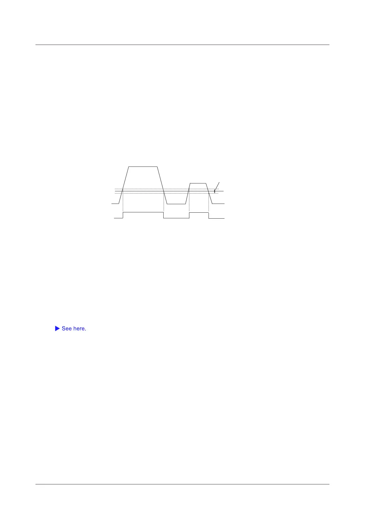
Trigger Level (Level)
You can set the FlexRay bus signal trigger level for each channel from CH1 to CH4.
Set the trigger level between the levels set for Idle and Data_0 so that the trigger circuit recognizes Data_1 and
Idle as H and Data_0 as L.
• You can set the trigger level in 0.01 division steps to a value that fits within the 8 divisions of the screen. For
example, when the voltage scale is 200 mV/division, you can set the trigger level in 2 mV steps.
• You can reset the trigger level to the current offset voltage by pressing RESET.
Hysteresis (Hysteresis)
Trigger level
Data_0
Data_0
Idle
Trigger comparator
output
Data_0
Bit Rate (Bit Rate)
Select the FlexRay bus signal’s transfer rate from one of the settings below.
2.5 Mbps, 5 Mbps, 10 Mbps
Bus Channel Assignment (Channel)
Select whether to use channel A or B of the FlexRay bus signal.
HF Rejection (HF Rejection)
Set these items for the trigger source.
This item is the same as those of the edge trigger.
4 Triggering
 Loading...


