4-37
IM DLM3054-01EN
Error Frame
Data Frame
or
Error Flag Error Delimiter
86 ≤ Error Flag ≤ 12
Dominant
If the mode is set to Error Frame, the
trigger point is the 6th error flag bit.
Stuff Error (Stuff Error)
The trigger point is the sample point of the bit that violates the bit stuffing rule.
CRCError (CRC Error)
CRC errors are indicated in the data-frame and remote-frame figures.
If multiple field types and frame types are combined, the trigger point is the point where the last type appears
on the time axis.
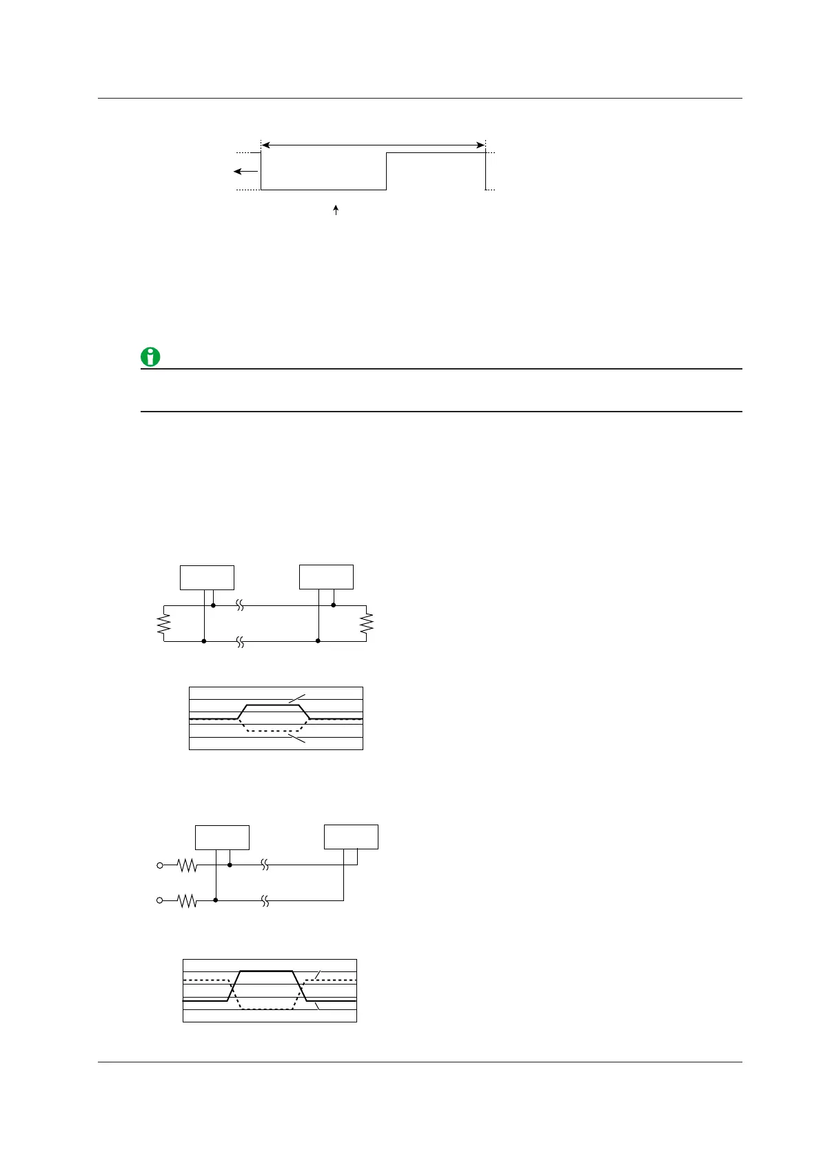
High speed CAN (ISO11898) and Low speed CAN (ISO11519-2)
The primary standards for the CAN physical layer are High-speed CAN (ISO11898) and Low-speed CAN
(ISO11519-2).
As shown in the following figure, the bus level is determined by the potential difference between two buses,
CAN_High and CAN_Low, in either standard.
0
1
2
3
4
5
CAN_High
CAN_Low
Node n
(Max:30)
Node 1
High speed CAN (ISO11898)
Recessive
CAN bus physical signal
CAN_High
CAN_Low
120 Ω
120 Ω
Transfer rate: 1 Mbps or less
0
1
2
3
4
5
2.2 kΩ
2.2 kΩ
CAN_High
CAN_Low
Node n
(Max:20)
Node 1
Low speed CAN (ISO11519-2)
Recessive
RecessiveDominant
CAN bus physical signal
CAN_Low
CAN_High
Transfer rate: 125 kbps or less
4 Triggering
 Loading...


