IM 04L20A01-01E
1-19
1
Explanation of Functions
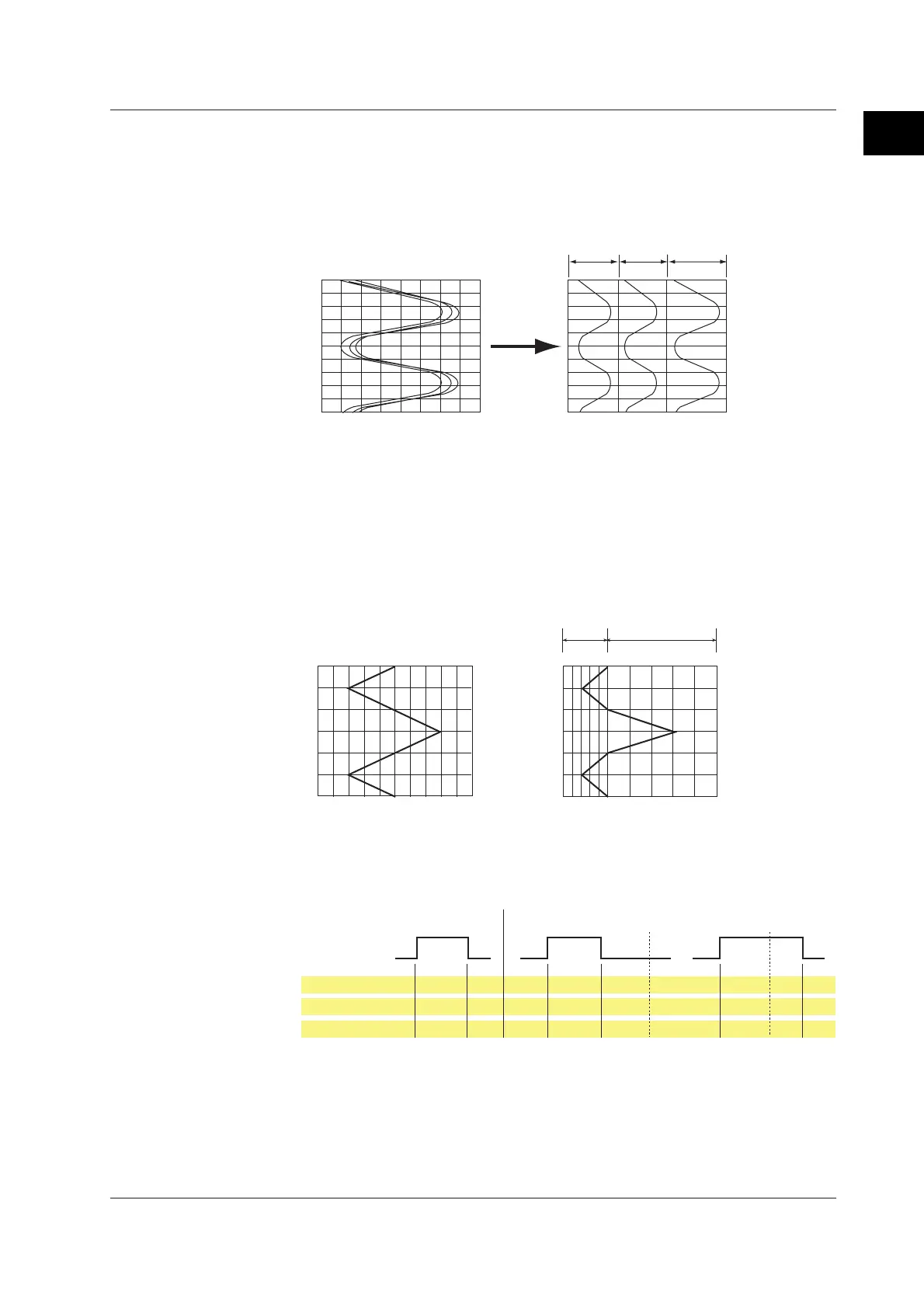
Zone Display
The display range (zone) can be set for each channel. In the example shown in the
figure below, channel 1 is displayed in the zone 0 to 30%, channel 2 in the zone 30 to
60%, and channel 3 in the zone 60 to 100%.
100%
0%
CH3CH2CH1
100%
30%0% 60%
Zone 3Zone 2
Zone 1
Normal display Zone display
Partial Expanded Display
By compressing a section of the display scale of the waveform, the remaining section
of is expanded. You specify a value on the display scale (boundary value) to be
moved to another position on the display scale (boundary value displacement
position). In the example shown below, 0 V (boundary value) is moved to the 30%
position of the display scale (boundary value displacement position). The section
below the boundary represents –6 V to 0 V and the section above the boundary
represents 0 V to 6 V.
100
100
30
0
50
0
6V
6V
0
–6V
–6V
0
Partial Expanded Dispaly
Normal Display
Expanded portion
Compressed portion
% of full display span
Measured valueMeasured value
Alarm Indication
The indications of preset alarm marks vary depending on the hold/non-hold setting of
alarm indication as follows.
Red None Red
None Red RedNone None None None None
Alarm type
Red Blue Red
Blue Red RedBlue Blue Blue Blue Blue
Measured value
Brinks
in red
Brinks
in red
Brinks
in green
Green Red RedGreen Green GreenGreen Green
Alarm mark
Alarm
Release
Alarm ACK Alarm ACK
Occurrence
Non hold Hold
For a description on the hold/non-hold setting of alarm indication, see section 1.3, “
Alarm
Function
.”
1.4 Display Function

 Loading...


