IM 04L20A01-01E
1-20
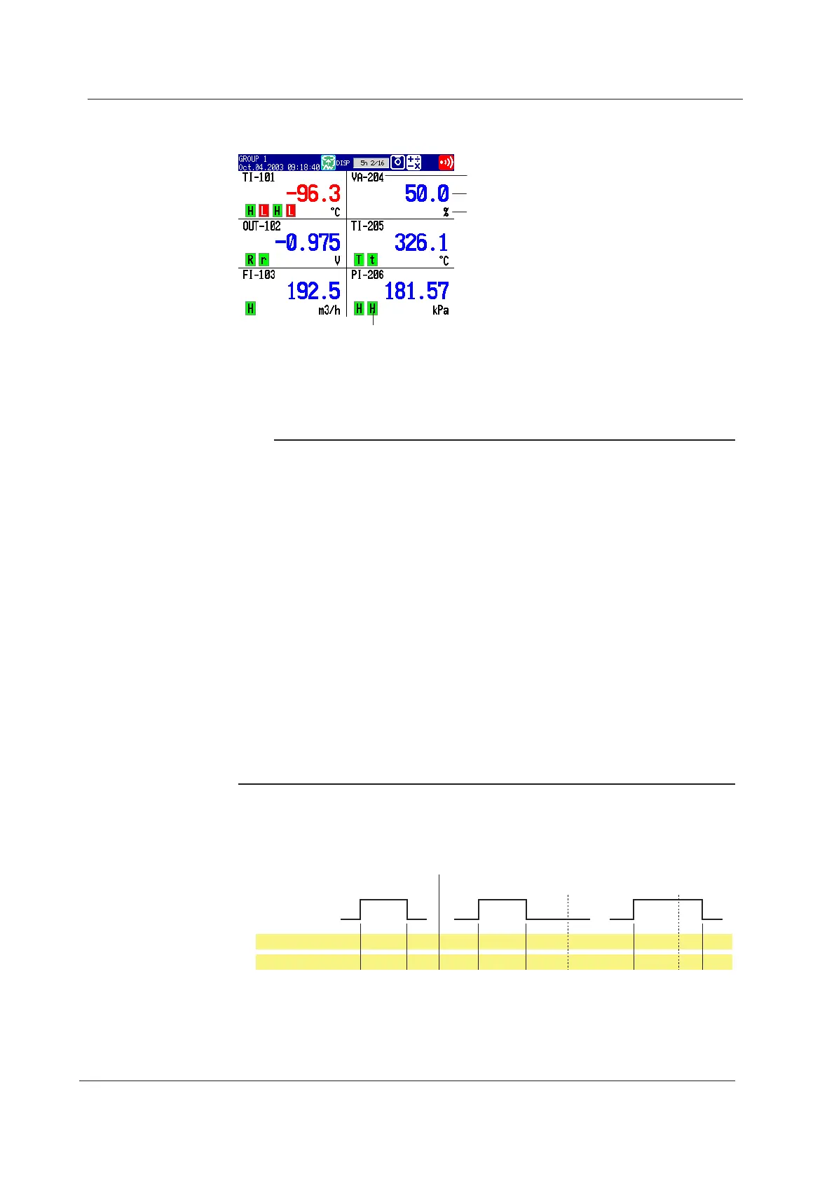
Digital Display
The measured data are displayed using numerical values in large size.
Measured value
Unit
Alarm mark
Tag/channel no.
Updating of the Numerical Display
Numerical display is updated every second. However, when the scan interval on the
FX106/FX112 is 2 s, the update rate is also 2 s.
Note
• Numerical Display of Measurement Channels (Common to Trend, Digital, and Bar
Graph Displays)
When the measured values of measurement channels are over range (see below), the
measured values are indicated as “+Over” or “–Over.” If a burnout is detected on a channel
assigned to the burnout detection function, "Burnout" is displayed for the measured value.
Otherwise, a numerical value is displayed.
Over Range of Measurement Channels
• For DC voltage input, over range occurs when the measured value of the measurement
channel exceeds ±5% of the measurable range. For example, the measurable range
when the measurement range is 2 V is –2.000 to 2.000 V. If the measured value exceeds
2.200 V, + over range occurs; if the measured value falls below –2.200 V, – over range
occurs.
• For thermocouple or RTD input, over range occurs when the measured value exceeds
approximately ±10°C of the measurable range. For example, the measurable range when
the measurement range is R is 0.0 to 1760.0°C. If the measured value exceeds
approximately 1770.0°C, + over range occurs; if the measured value falls below
approximately –10.0°C, - over range occurs.
• Numerical display of computation channels (common to trend, digital, and bar graph
displays)
See section 1.6, “
Computation Function and Report Function (/M1, /PM1 Option)
.”
Alarm Indication
The indications of preset alarm marks vary depending on the hold/non-hold setting of
alarm indication as follows.
Red Blue Red
Blue Red RedBlue Blue Blue Blue Blue
Measured value
Brinks
in red
Brinks
in red
Brinks
in green
Green Red RedGreen Green GreenGreen Green
Alarm mark
Alarm
Release
Alarm ACK Alarm ACK
Occurrence
Non hold Hold
For a description on the hold/non-hold setting of alarm indication, see section 1.3, “
Alarm
Function
.”
1.4 Display Function

 Loading...


