OPERATION
Axio Imager Illumination and contrast methods Carl Zeiss
M70-2-0020 e 06/2009 430000-7344-001 173
4.9.10 Setting reflected-light TIC
(1) Application
The reflected-light TIC technique (microinterferometry; TIC = Total Interference Contrast in circularly
polarized light) can be used to image and measure object structures available in different azimuths.
(2) Instrument equipment
− Axio Imager MAT with connected and adjusted
HAL 100 halogen illuminator.
− EC Epiplan-Neofluar, Epiplan objectives
additionally labeled with "DIC" or "Pol".
− 6x20 compensator mount or 4-position
modulator turret
− 6x20 TIC slider with accompanying C DIC P&C
reflector module.
(3) Setting reflected-light TIC
• Place the specimen (e.g. a step-shaped object)
on the stage and prepare the microscope as
described in Section
4.9.7 for reflected-light
brightfield.
• Rotate reflector turret to swing C DIC P&C
reflector module into the light path.
• Push 6x20 TIC slider into 6x20 compensator mount (4-129/4) or rotate turret wheel (4-130/5) of
4-position modulator turret (
4-130/6) into TIC-Position (TIC). In the field of view, colored interference
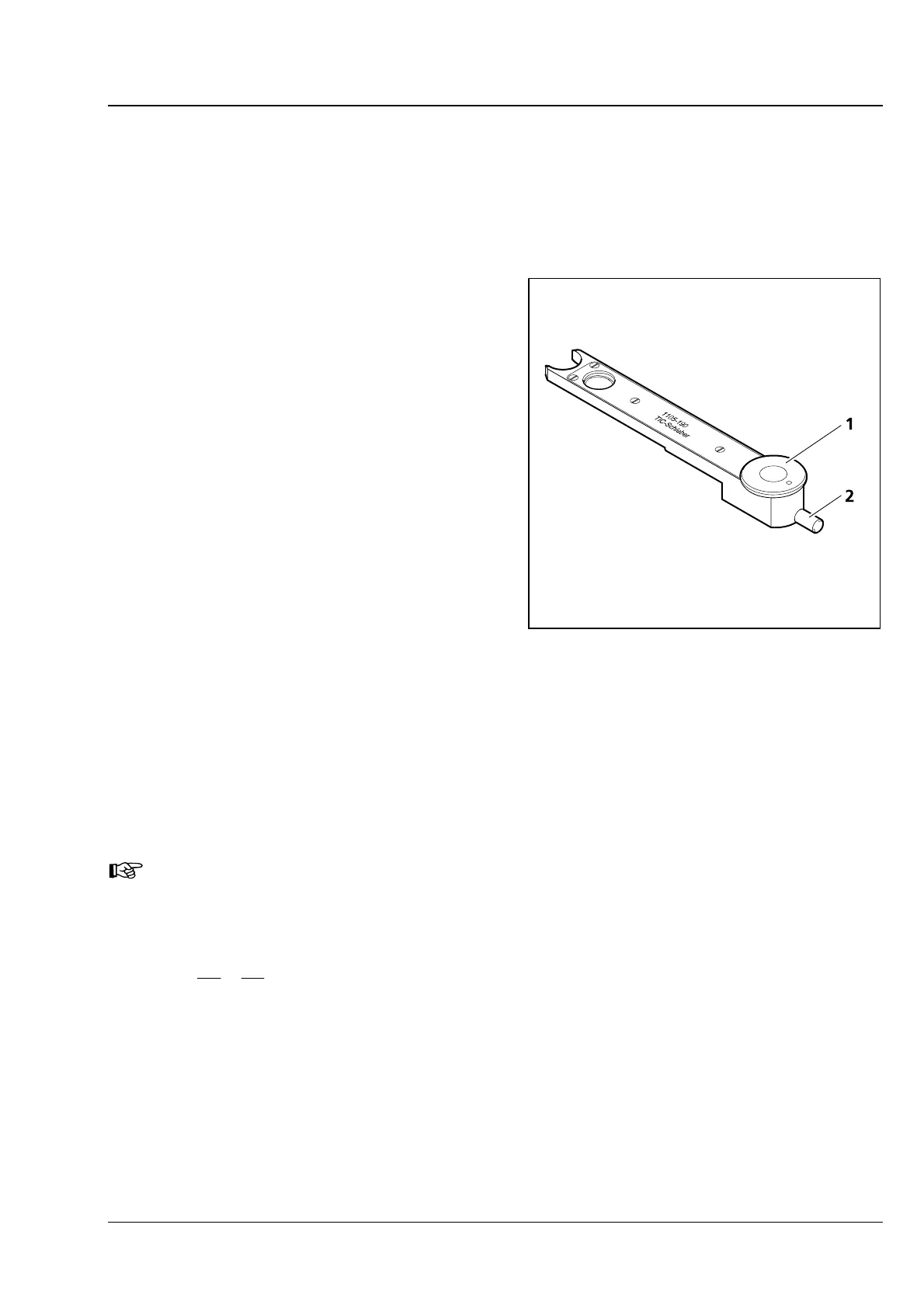
fringes appear. Turn setscrew (
4-132/2) of the TIC slider or the modulator turret to shift the black
interference fringe until it appears to be in the center of the field of view.
• To select the structure to be measured, turn control wheel (4-132/1) of TIC slider or modulator turret
until the interference fringe system is vertical to the splitting direction of the specimen (see Fig
4-133).
The interference fringes can be shifted by means of setscrew (
4-132/2) of the TIC slider or the
modulator turret.
Please refer to Section
4.9.9 (5) for the use of the motorized four-position modulator turret for
the reflected-light TIC technique.
The step height is determined subsequently according to the following formula:
a2
b
2
n
d
λ
=
Δ
=
where: d = step height in nm
n = refractive index of the environment, usually air (n = 1)
Δ = path difference
a = spacing of interference fringes
b = offset of interference fringes at the step
λ = wavelength of the illumination in nm
Fig. 4-132 6x20 TIC slider