OPERATION
Axio Imager Mechanical Stage 75x50 mot. CAN Carl Zeiss
M70-2-0020 e 06/2009 430000-7344-001 89
4.6 Mechanical Stage 75x50 mot. CAN
4.6.1 Assembling Mechanical Stage 75x50 mot. CAN
− While assembling the stage, take care that you do not disconnect any existing cable
connections from the stage motors.
Mixing up of plugs at the stage motors may lead to the destruction of the integrated
measuring systems!
− After you have unpacked the mechanical stage, remove the transport lock (
4-15/2) on the
underside of the mechanical stage.
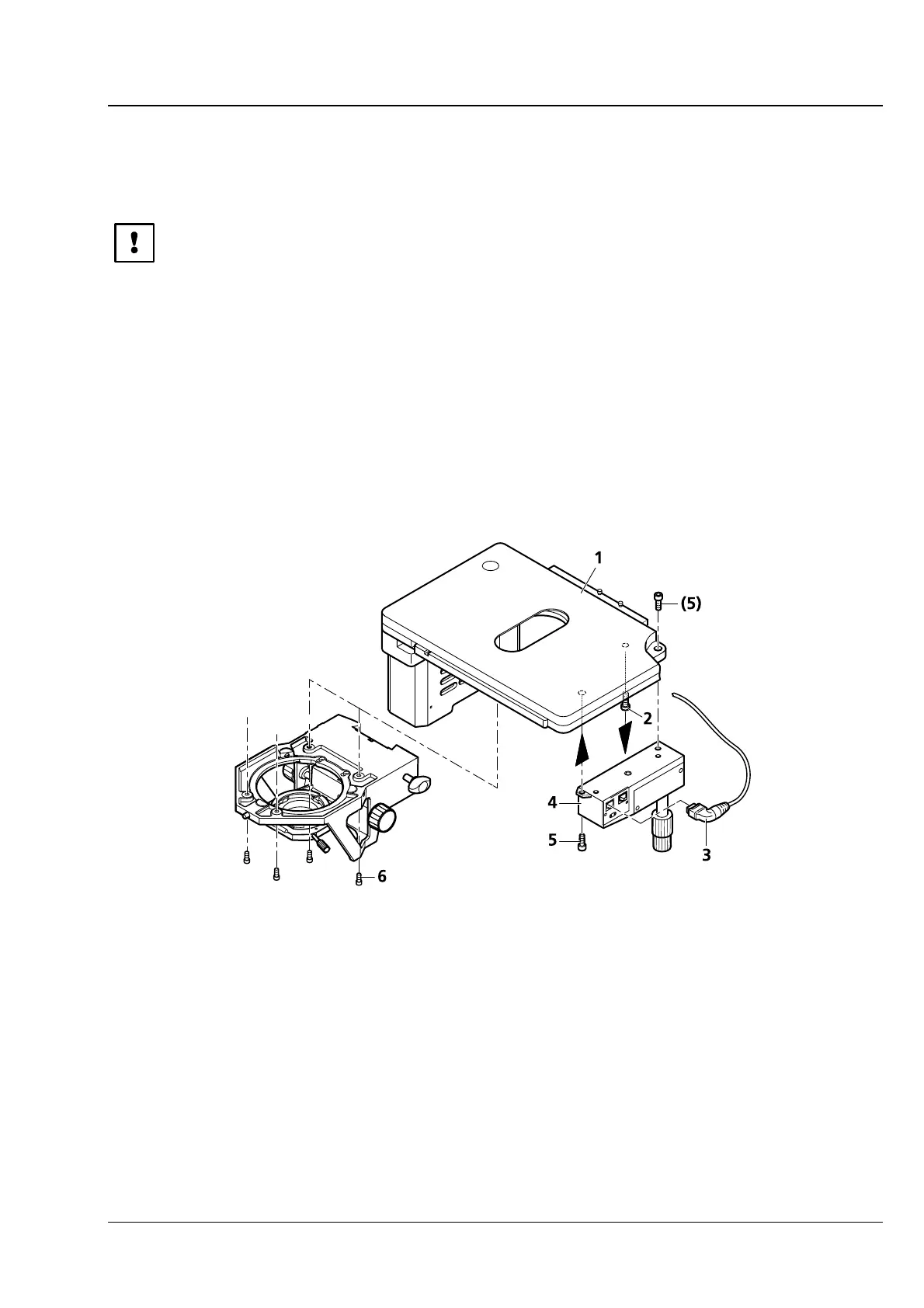
• Slide the stage plate (4-15/1) frontward and fasten coaxial drive (4-15/4) to the underside of the stage
using two screws (
4-15/5).
• Plug angled CAN bus connector (4-15/3) into one of the two sockets on the coaxial drive.
• Place mechanical stage (4-15/1) onto stage carrier in a way that the holes in the underside of the
mechanical stage coincide with the through holes of the stage carrier.
• Using the angled Allen key (SW 3), screw four screws (4-15/6) from the bottom into the underside of
the stage with the shorter screws being inserted in the front holes.
1 Mechanical stage 75x 50 mot. CAN
2 Transport lock (screw)
3 Angled CAN bus connector (100-0600-144)
4 Electronic coaxial drive CAN
5 Fastening screws on coaxial drive
6 Fastening screws on stage carrier
Fig. 4-15 Assembling Mechanical Stage 75x50 mot. CAN