START-UP
Axio Imager Changing the filter set in the reflector module FL P&C Carl Zeiss
M70-2-0020 e 06/2009 430000-7344-001 47
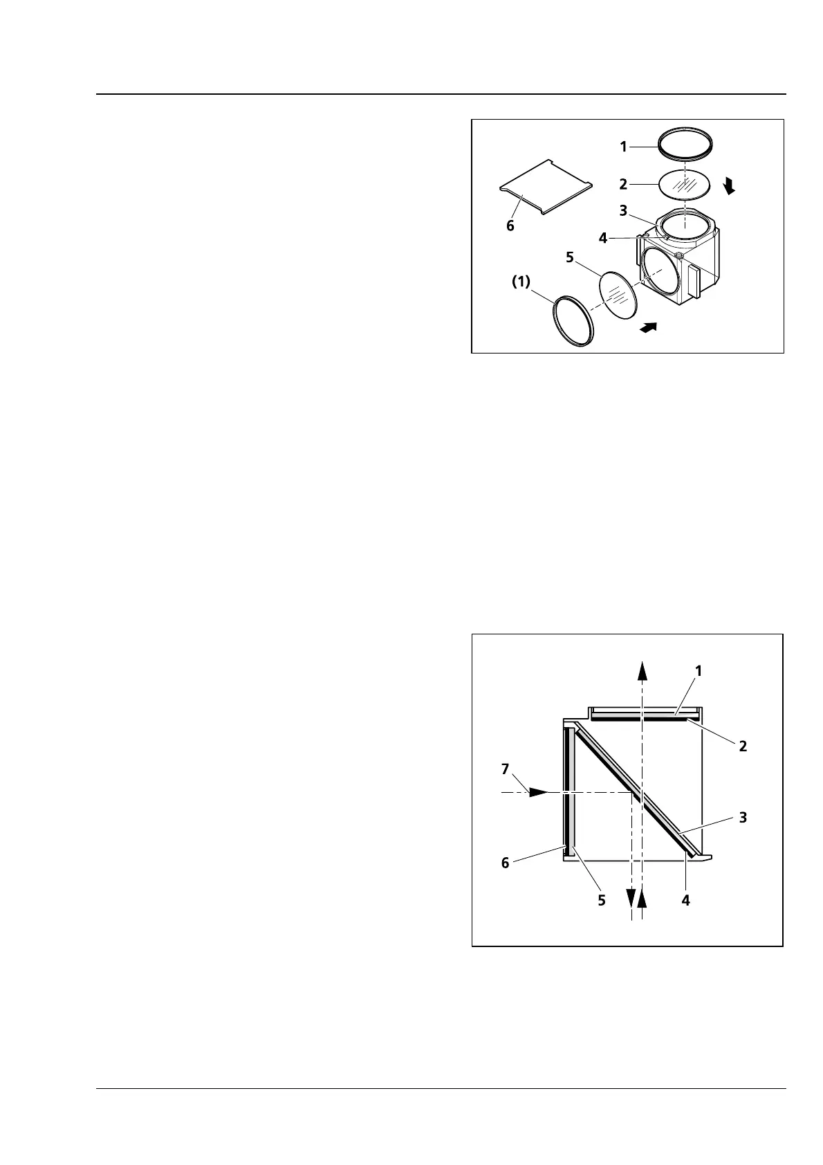
• Remove reflector module FL P&C (3-23/3) from
the reflector turret and put it down (refer to
Section
3.19).
• Use mounting plate (3-23/6) of tool kit to
unscrew retaining ring (
3-23/1).
• Turn the reflector module round and let the
filter (
3-23/2 or 5) drop out on a soft surface.
• Insert the barrier filter (emission filter) at
(
3-23/2), the exciter filter at (3-23/5). Secure
both filters by means of retaining rings (
3-23/1).
Barrier filter and exciter filter may be provided with a designation and an arrow on their circumference.
The arrow indicates the direction the particular filter is to be installed in the reflector module; it must
always point inwards (refer to arrows in Fig.
3-23).
To minimize image offset during multiple fluorescence image captures, an additional label can be
provided on the barrier filter to indicate the position of the wedge angle.
This label should be aligned to the orientation groove (
3-23/4) when you insert the barrier filter in the
reflector module used. This is to ensure that the wedge angle of the barrier filters is in the same, defined
position in the reflector modules used thus compensating or minimizing the already minimal module-to-
module image shift when Zeiss filter sets are used.
If it is necessary to mount filters that do not carry
any directional mark (arrow), it is advisable to
follow this procedure:
Mount the filters with the reflective dielectric layers
in such a way that the reflective layer (
3-24/6) on
the exciter filter (
3-24/5) points outwards (relative
to the reflector module). On the barrier filter
(
3-24/1), the reflective layer (3-24/2) points inwards
(Fig.
3-24).
The reflective layer (
3-24/4) of the beam splitter
(
3-24/3) should point downward when in its
mounting position.
The arrows (
3-24/7) mark the illumination and
imaging beam path.
Fig. 3-23 Changing the filter set in reflector
module FL P&C
Fig. 3-24 Installing filter and beam splitter