MSC-3 Instruction Manual
The MSC-3 internal cooling fans will be forced ON while ever the S04 FAN OVERRIDE parameter is set
to ENABLED. When DISABLED, the fans will operate according to internal temperature measurements.
Temperature sensor display
The temperature sensor menu contains a set of displays that show the reading of each sensor within the
MSC3 chassis. Press Enter to gain access to these displays.
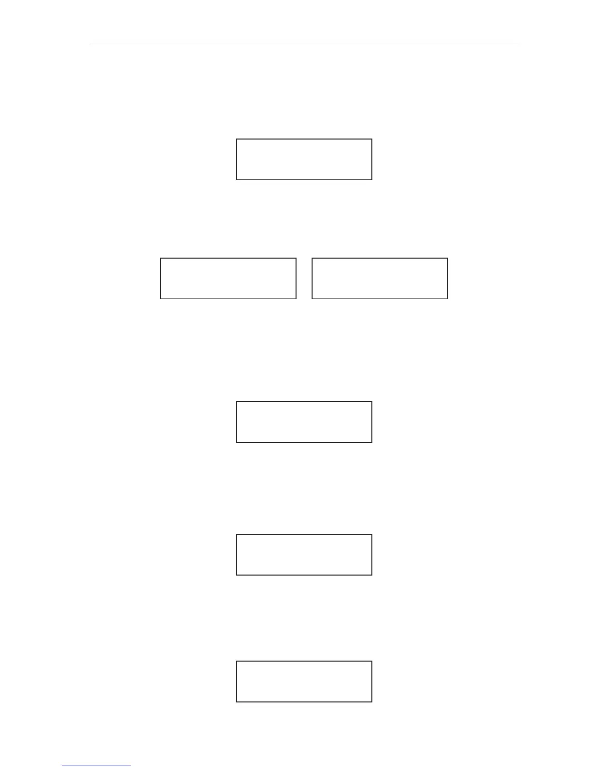
An example of one such display is:
*T1 33.2 degC
Ths 33.2 degC
For chassis A,B and C this is the only temperature display as only one sensor measures the internal heat
sink temperature.
For chassis D there are several temperature sensors not all are mounted on the internal heat sinks. In the
example given below there are 2 temperature sensors. The displays for sensor T1 and sensor T2 are:
*T1 33.2 degC
Ths 33.2 degC
T2 35.7 degC
Ths 33.2 degC
The * symbol before T1 indicates that T1 is used in the calculation of the heat sink temperature Ths. In
this example T2 is not involved. The heat sink temperature is the maximum value of all sensors displayed
with the * symbol.
Digital Input Display
This display makes it possible to view the state of the digital input terminals without the hazards of
removing the cover of the drive. An activated input is represented by a “1” and a deactivated input is
represented by a “0”. The state of each digital input terminal is displayed on the bottom line:
DI (2,3,4,5,6)
0,0,0,0,1
In this example terminals 2, 3, 4 and 5 are currently deactivated. Terminal 6 however is activated.
Terminal 6 is the “EN” (or Enable) input.
Analogue Input Display
This display makes it possible to view the state of the analogue input without the hazards of removing
the cover of the drive. The value displayed is either “mA” or “V” depending on the conguration of the
input.
AI (10,11) 5.09V
This example tells that the conguration is for a voltage input and the value measured is 5.09V
Relays Display
This display makes it possible to view the state of the relays. An energised relay is represented by a “1”
and a de-energised relay is represented by a “0”.
RL1 (15,16) 0
Rl2 (17,18) 0
This example reveals that both relays should be de-energised.