MSC-3 Instruction Manual
Application: Return air fan
This setup is for a typical HVAC return air fan application that requires speed control from a remote
signal source for normal operation, and local control from the front console. Prior to commissioning, you
will need to know the type of speed signal that is to be used (0-10V, 4-20mA etc).
Procedure
STEP 1 Complete the power wiring according to the instructions on pages 9 to 18
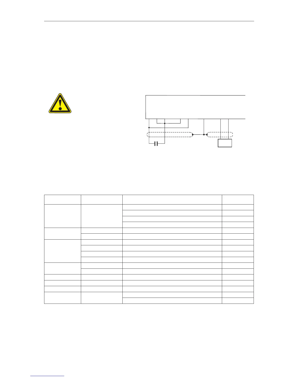
STEP 2 Connect the control and signal wiring as shown. type.
CAUTION
Do not connect the wire to
terminal 6 yet.
The terminal conguration
should not be changed while
the MSC-3 is enabled.
STEP 3 Follow the instructions on page 47 for MSC-3 startup, setting the parameters
according to the table below. Alternate values may be used to suit the application.
Menu Menu Item Suggested Setting
Page for detailed
information
G00 INPUT/OUTPUT G01 Inpt fxn CFG
(Input terminal
conguration)
I02 ~STOP = D1(2) 91
I00 FWD & LATCH = D2(3) 90
I08 ESO = D3(4) 93
I11 REMOTE = D4(5) 93
G00 INPUT/OUTPUT G03 RL1 G030 RL1 Signal = RUN (default) 98
G04 Rl2 G040 RL2 Signal = TRIP (default) 100
B00 MOTOR B01 MOTOR VOLTS Motor nameplate voltage 71
B02 MOTOR AMPS Motor nameplate amps 71
B03 MOTOR HZ Motor nameplate frequency 71
B04 MOTOR RPM Motor nameplate RPM 72
D00 PROTECTION D01 CURRENT LIM Motor nameplate current +10% 78
D02 I2t Thermal overload Motor nameplate current 78
E00 STOP/START E03 AUTO RESTART E030 ARs ALLOWED = 5 82
E04 Reset by PF ENABLED 83
F00 REFERENCES F01 REMOTE REF AI(10,11) 85
C00 PERFORMANCE C03 RAMP C030 ACCEL TIME = 60 sec 74
C031 DECEL TIME = 60 sec 74
STEP 4 Now connect the wire to terminal 6.
End of procedure