MSC-3 Start Up
Extended Features Digital Input Display
Refer to the “Extended Features Cards” section for setup information. When one or more extended
features cards are tted extra displays, values and choices appear throughout the menu system. Like the
standard digital and analogue I/O, the state of the I/O found on the Extended Feature cards are viewable.
In the case of extended feature card, an activated input is represented by a “1” and a deactivated input
is represented by a “0”.
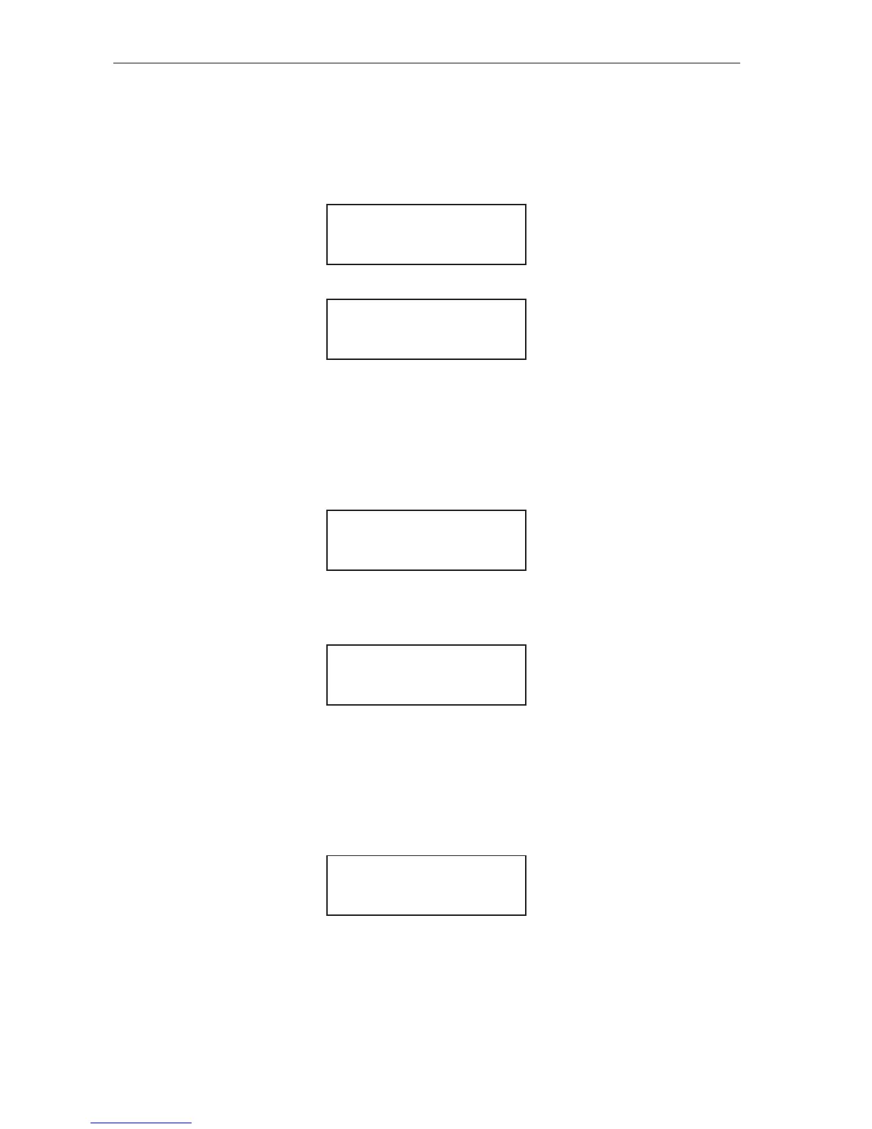
An example input display of an Extended Features Card tted to the left hand side option connector is:
DI (31,33,35,37)
0, 0, 0, 0
An example input display of an Extended Features Card tted to the right hand side option connector is:
DI (51,53,55,57)
0, 0, 0, 0
Extended Features Analogue Input Display
Refer to the “Extended Features Cards” section for setup information. When one or more extended
features cards are tted extra displays, values and choices appear throughout the menu system. Like the
standard digital and analogue I/O, the state of the I/O found on the Extended Feature cards are viewable.
The state of the analogue and thermistor input are revealed on the Extended Features Analogue Input
Display.
An example input display of an Extended Features Card tted to the left hand side option connector is:
AI (32,34) 0.09V
TH (40,42) 1.0K
In this example the analogue input is congured as a voltage input. An example input display of an
Extended Features Card tted to the right hand side option connector is:
In this example the analogue input is congured as a voltage input.
AI (52,54) 0.00V
TH (60,62) 1.0K
Extended Features Output Display
Refer to the “Extended Features Cards” section for setup information. When one or more extended
features cards are tted extra displays, values and choices appear throughout the menu system. Like
the standard digital and analogue I/O, the state of the I/O found on the Extended Feature cards are
viewable. The state of the analogue output and digital output are revealed in the Extended Features
Output Display.
An example output display of an Extended Features Card tted to the left hand side option connector is:
DO (39,41) 0
AO (36,38) 1.76V
An activated digital output is represented by a “1” and a de-activated digital output is represented by a
“0”. In this example the digital output is de-activated.