MSC-3 Instruction Manual
Application: Cooling tower fan with reverse acting internal PID
This setup is for a typical cooling tower fan application that requires water temperature control using a
water temperature transducer and the PID controller function provided by the MSC-3 extended features
option board. Prior to commissioning, you will need to know the type of temperature sensor signal that is
to be used (0-10V, 4-20mA etc).
Procedure
STEP 1 Complete the power wiring according to the instructions on pages 9 to 18
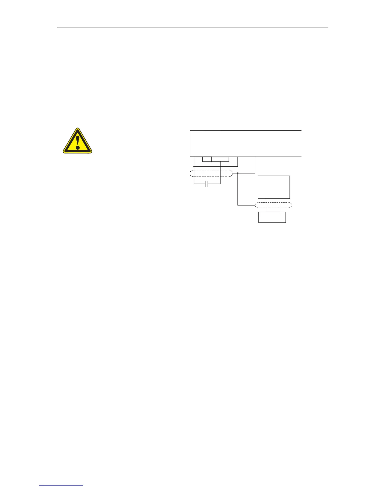
STEP 2 Connect the control wiring as shown.
CAUTION
Do not connect the wire
to terminal 6 yet.
The terminal conguration
should not be changed
while the MSC-3 is
enabled.
MSC-3 Extended
Features Option
IN+ IN-
32 34
Water temperature
transducer
RUN
STEP 3 Connect the signal wiring from the water temperature transducer as shown. Consult the
transducer manufacturer’s literature for power supply requirements of the transducer.
Set the switches on the Extended Features Option to suit the type of signal.
Go to the G00 INPUT/OUTPUT menu and select G10 AI(32,34). Set G100 for the type of
input signal (mA or voltage). Set G101 Min Input and G102 Max Input to reect the range
of the signal, typically 4-20mA or 0-10V. For more information, see page 89.
See page 45
for additional
details