Control connections and conguration
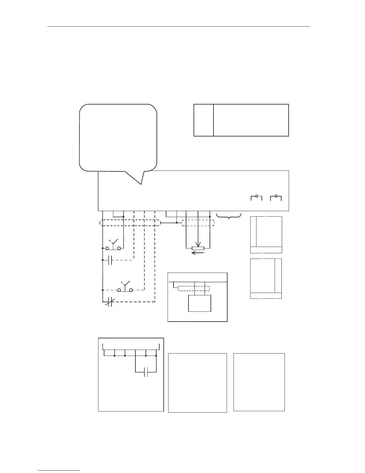
HVAC Terminals Typical Connection Diagram – Terminal Cong 3
General
This section shows the typical conguration applicable to pump and fan drives in the HVAC industry.
Typically these will be controlled from an external speed signal, frequently supplied from the output of
a building management system. Specic setup instructions are provided for the more common HVAC
applications in the sections that follow this.
i
Essential Services Override
(ESO)
See page 51 for detailed
information
See page 43
for details
Optional Wiring
If selection between
local and remote is
not required, place a
link between terminals
1 and 5. If the output
disable is not required
place link between
terminals 1 and 6
Local / Remote
In “local” the MSC-3
is controlled from
the front panel
console. In “remote”
the MSC-3 is
controlled from the
terminal strip.
i
The function of terminals
D1...4 are programmable. In
this conguration the following
functions are assigned to the
terminals:
I02 ~ STOP D1
I00 FWD & LATCH D2
I08 ESO D3
I11 REMOTE D4