Chapter 35 Product Specifications
N4100 User’s Guide
259
Make sure that the Ethernet cable connection between the N4100 and the switch
or router conforms to the following pin assignments.
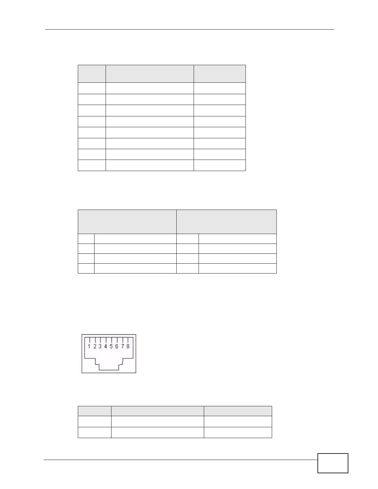
LAN Ports
The following figure and table describe the Ethernet cable pin assignments for the
LAN port.
Figure 125 LAN Port Cable Pin Assignments
Table 71 WAN Port Cable Pin Assignments
PIN NO
RJ-45 SIGNAL
ASSIGNMENT
DESIGNATION
1 Output Transmit Data + TD+
2 Output Transmit Data - TD-
3 Input Transmit Data + RD+
4 Unused N/U
5 Unused N/U
6 Input Transmit Data - RD-
7 Unused N/U
8 Unused N/U
Table 72 WAN Port Cable Pin Assignments
ETHERNET DEVICE
(SWITCH/HUB/ROUTER ETC.)
N4100
1 RD+ 1 TD+
2 RD- 2 TD-
3TD+ 3 RD+
6TD- 6 RD-
Table 73 LAN Port Cable Pin Assignments
PIN NO RJ-45 SIGNAL ASSIGNMENT DESIGNATION
1 Input Transmit Data + RD+
2 Input Transmit Data - RD-

 Loading...