Configuring S200 I/O Modules Section 4 Configuration
160 9ARD000014-600 A
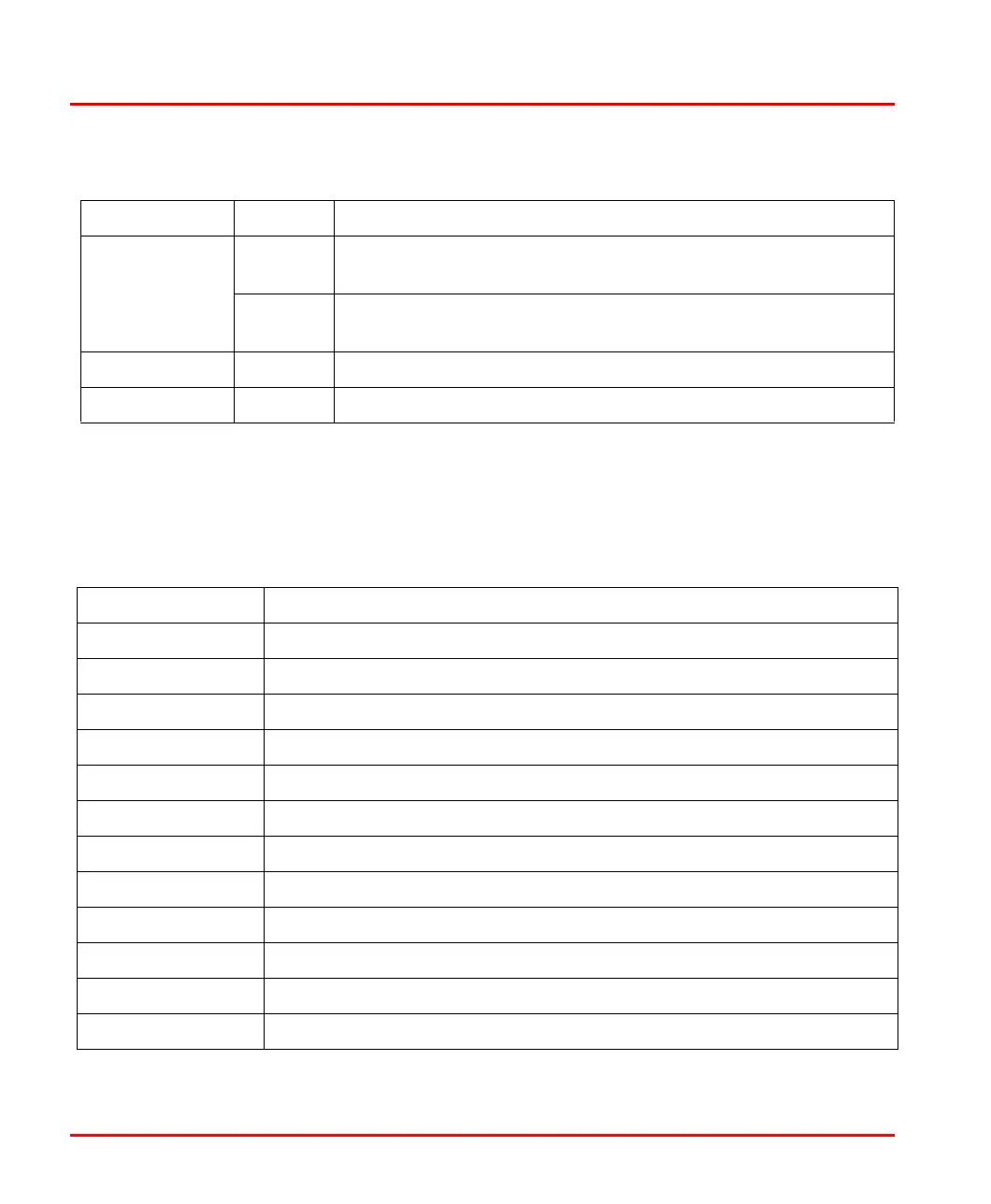
The Table 28 below gives description about settings which needs to be applied on
output channels and the interpretation of data received on the Input channels for
200-IP4.
Ctrl Out 1 Bit 14 Store Reset bit - A positive edge on this bit resets Store X in
Signals.
Bit 15 Store Reset bit - A positive edge on this bit resets Preset
Reached in Signals.
Preset Out 0 Bits 00-15 Preset 0 - Value to load or compare with counter 0
Preset Out 1 Bits 00-15 Preset 1 - Value to load or compare with counter 1
Tabl e 28. Description of Channels for 200-IP4
Channel Name Definition
Value in Period16 0 It gives 16 Bit period measurement for channel 0
Value in Period16 1 It gives 16 Bit period measurement for channel 1
Value in Period16 2 It gives 16 Bit period measurement for channel 2
Value in Period16 3 It gives 16 Bit period measurement for channel 3
Value in Period32 0 It gives 32 Bit period measurement for channel 0
Value in Period32 1 It gives 32 Bit period measurement for channel 1
Value in Period32 2 It gives 32 Bit period measurement for channel 2
Value in Period32 3 It gives 32 Bit period measurement for channel 3
Value in Counter 0 This channel shows pulse counter value for channel 0
Value in Counter 1 This channel shows pulse counter value for channel 1
Value in Counter 2 This channel shows pulse counter value for channel 2
Value in Counter 3 This channel shows pulse counter value for channel 3
Table 27. Description of Channels for 200-IP2 (Continued)
Channel Name Bit Definition

 Loading...


