274 Actual signals and parameters
Starting order counter
The operation of the starting-order counter:
• The relay output parameter definitions (1401…1403 and
1410) establish the initial motor sequence. (The lowest
parameter number with a value 31 (PFC) identifies the
relay connected to 1PFC, the first motor, and so on.)
• Initially, 1PFC = speed regulated motor, 2PFC = 1st
auxiliary motor, etc.
• The first Autochange shifts the sequence to: 2PFC =
speed regulated motor, 3PFC = 1st auxiliary motor, …,
1PFC = last auxiliary motor.
• The next Autochange shifts the sequence again, and so
on.
• If the Autochange cannot start a needed motor because
all inactive motors are interlocked, the drive displays an
alarm (2015 PFC I LOCK).
• When the drive power supply is switched off, the counter
preserves the current Autochange rotation positions in
permanent memory. When power is restored, the
Autochange rotation starts at the position stored in
memory.
• If the PFC relay configuration is changed (or if the PFC
enable value is changed), the rotation is reset according
to parameters 1401…1403 and 1410.
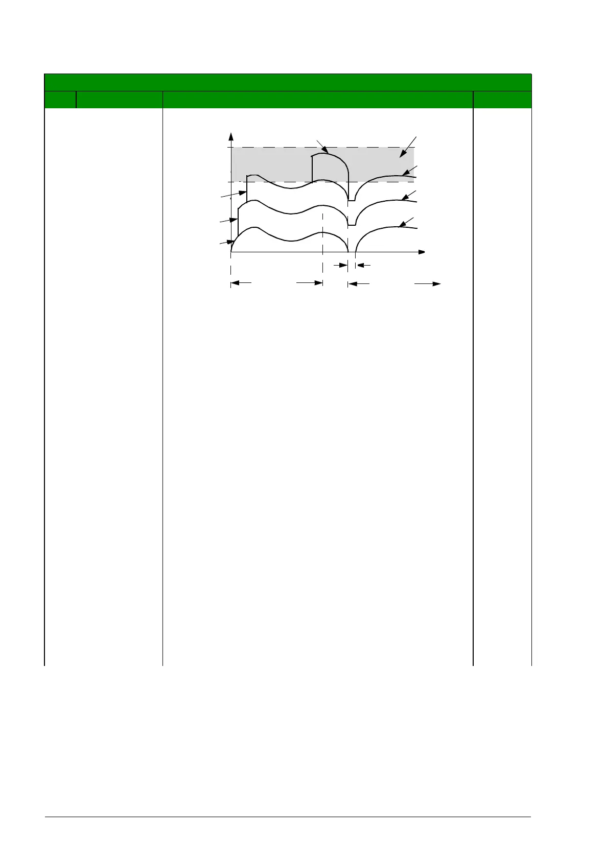
All parameters
No. Name/Value Description Def/FbEq
B
A
A = Area above 8119 AUTOCHNG LEVEL – Autochange
not allowed
B = Autochange occurs
1PFC, etc. = PID output associated with each motor.
t
8118
100%
8119
3PFC
2PFC
1PFC
PID output
4PFC
2PFC
3PFC
4PFC
8118
8122