280 Actual signals and parameters
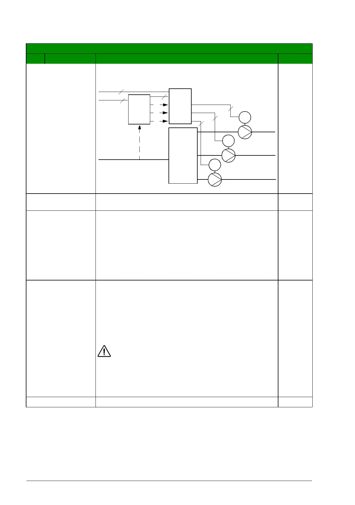
Example: In the diagram below, the pumping station’s outlet
flow is controlled by the measured inlet flow (A).
NO Disables Regulator by-pass control. The drive uses the
normal PFC reference 1106 REF2 SELECT.
0
YES Enables Regulator by-pass control.
The process PID regulator is bypassed. Actual value of PID
is used as the PFC reference (input). (Normally 1106 REF2
SELECT is used as the PFC reference.)
The drive uses the feedback signal defined by 4014 FBK
SEL (or 4114) for the PFC frequency reference.
The first figure for parameter 8121 shows the relation
between the control signal 4014 FBK SEL (or 4114) and the
speed regulated motor’s frequency in a three-motor system.
1
8122 PFC START
DELAY
Sets the start delay for speed regulated motors in the
system. Using the delay, the drive works as follows:
• Switches on the contactor of the speed regulated motor,
connecting the motor to the drive power output.
• Delays motor start for time 8122 PFC START DELAY.
• Starts the speed regulated motor.
• Starts auxiliary motors. See parameter 8115 AUX MOT
START D for delay.
WARNING! Motors equipped with star-delta starters
require a PFC start delay.
After the drive relay output switches a motor on, the star-
delta starter must switch to the star-connection and then
back to the delta-connection before the drive applies power.
So, the PFC start delay must be longer than the time setting
of the star-delta starter.
0.50 s
0.01…10.00 s Delay time 1 = 0.01 s
All parameters
No. Name/Value Description Def/FbEq
M
3~
M
3~
M
3~
P1
P2
P3
P1
P2
P3
3
3
3
3
3
3
A
Mains 3~
Inlet pipe
Outlet
pipe 1
Outlet
pipe 2
Outlet
pipe 3
Con-
tactors
Sewage
tank
Drive