Actual signals and parameters 279
DI5 Enables the Interlock function and assigns a digital input
(starting with DI5) to the interlock signal for each PFC relay.
These assignments are defined in the following table and
depend on:
• the number of PFC relays (number of parameters
1401…1403 and 1410 with value = 31 [PFC])
• the Autochange function status (disabled if 8118
AUTOCHNG INTERV = 0.0, and otherwise enabled).
5
8121 REG BYPASS
CTRL
Selects Regulator by-pass control. When enabled,
Regulator by-pass control provides a simple control
mechanism without a PID regulator.
NO
Use Regulator by-pass control only in special applications.
All parameters
No. Name/Value Description Def/FbEq
No.
PFC
relays
Autochange disabled
(Parameter 8118)
Autochange enabled
(Parameter 8118)
0 DI1…DI4: Free
DI5: Speed reg motor
Not allowed
1 Not allowed DI1…DI4: Free
DI5: First PFC relay
2…5 Not allowed Not allowed
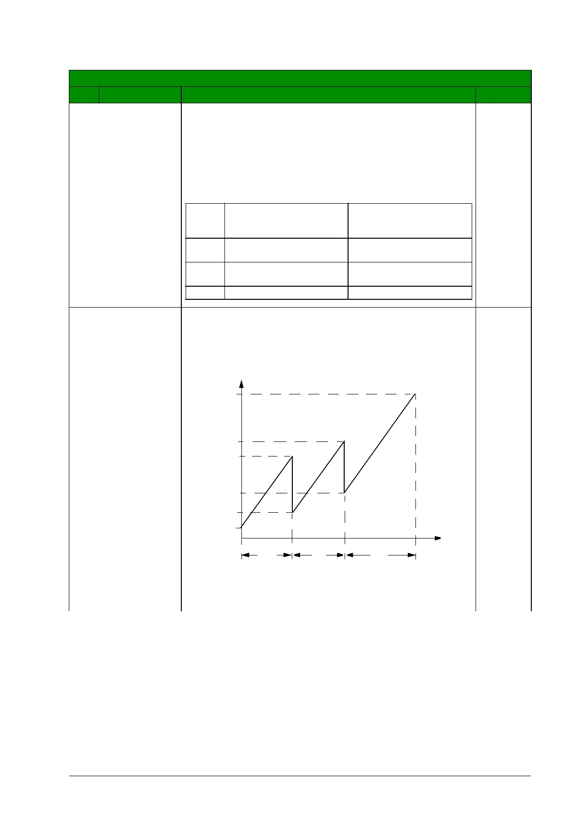
A = No auxiliary motors running
B = One auxiliary motor running
C = Two auxiliary motors running
A B
C
(%)
8109
f
OUT
f
MAX
8110
8113
8112
f
MIN
4014