278 Actual signals and parameters
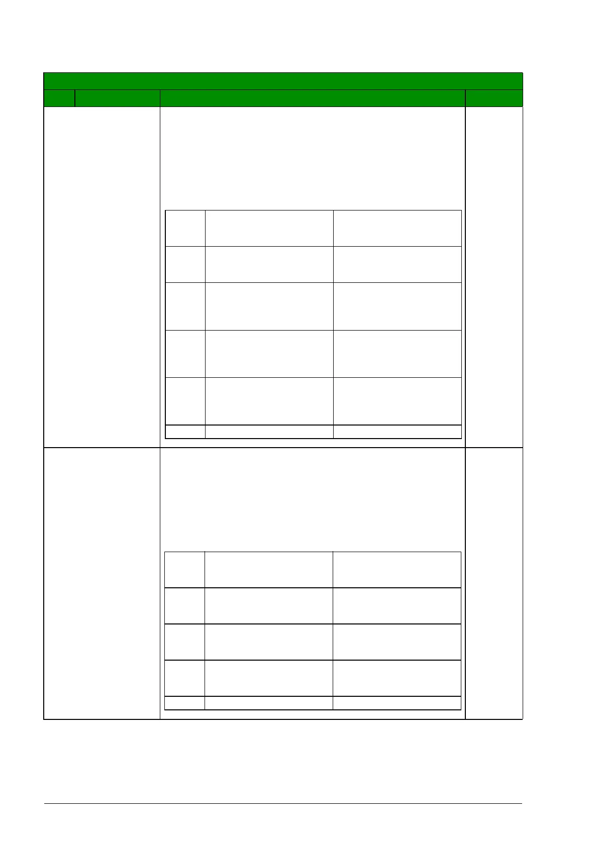
DI3 Enables the Interlocks function and assigns a digital input
(starting with DI3) to the interlock signal for each PFC relay.
These assignments are defined in the following table and
depend on:
• the number of PFC relays (number of parameters
1401…1403 and 1410 with value = 31 [PFC])
• the Autochange function status (disabled if 8118
AUTOCHNG INTERV = 0.0, and otherwise enabled).
3
DI4 Enables the Interlock function and assigns a digital input
(starting with DI4) to the interlock signal for each PFC relay.
These assignments are defined in the following table and
depend on:
• the number of PFC relays (number of parameters
1401…1403 and 1410 with value = 31 [PFC])
• the Autochange function status (disabled if 8118
AUTOCHNG INTERV = 0.0, and otherwise enabled).
4
All parameters
No. Name/Value Description Def/FbEq
No. of
PFC
relays
Autochange disabled
(Parameter 8118)
Autochange enabled
(Parameter 8118)
0 DI1…DI2: Free
DI3: Speed reg motor
DI4…DI5: Free
Not allowed
1 DI1…DI2: Free
DI3: Speed reg motor
DI4: First PFC relay
DI5…DI5: Free
DI1…DI2: Free
DI3: First PFC relay
DI4…DI5: Free
2 DI1…DI2: Free
DI3: Speed reg motor
DI4: First PFC relay
DI5: Second PFC relay
DI1…DI2: Free
DI3: First PFC relay
DI4: Second PFC relay
DI5: Free
3 Not allowed DI1…DI2: Free
DI3: First PFC relay
DI4: Second PFC relay
DI5: Third PFC relay
4…5 Not allowed Not allowed
No. of
PFC
relays
Autochange disabled
(Parameter 8118)
Autochange enabled
(Parameter 8118)
0 DI1…DI3: Free
DI4: Speed reg motor
DI5: Free
Not allowed
1 DI1…DI3: Free
DI4: Speed reg motor
DI5: First PFC relay
DI1…DI3: Free
DI4: First PFC relay
DI5: Free
2 Not allowed DI1…DI3: Free
DI4: First PFC relay
DI5: Second PFC relay
3…5 Not allowed Not allowed