128 Parameters
12.15 AI1 unit selection Selects the unit for readings and settings related to analog
input AI1.
Note: This setting must match the corresponding
hardware setting on the drive control unit. See the
hardware manual of the drive and the default control
connections for the macro in use in chapter Control
macros. Control board reboot (either by cycling the power
or through parameter 96.08 Control board boot) is
required to validate any changes in the hardware settings.
V
VVolts. 0
mA Milliamperes. 1
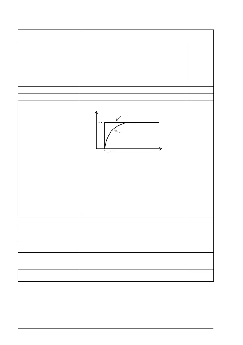
12.16 AI1 filter time Defines the filter time constant for analog input AI1.
Note: The signal is also filtered due to the signal interface
hardware (approximately 0.25 ms time constant). This
cannot be changed by any parameter.
0.100 s
0.000…30.000 s Filter time constant. 1000 = 1 s
12.17 AI1 min Defines the minimum site value for analog input AI1.
Set the value actually sent to the drive when the analog
signal from plant is wound to its minimum setting.
4.000 mA or
0.000 V
0.000…20.000 mA or
0.000…10.00 V
Minimum value of AI1. 1000 = 1 mA
or V
12.18 AI1 max Defines the maximum site value for analog input AI1.
Set the value actually sent to the drive when the analog
signal from plant is wound to its maximum setting.
20.000 mA
or 10.00 V
0.000…20.000 mA or
0.000…10.00 V
Maximum value of AI1. 1000 = 1 mA
or V
No. Name/Value Description Default
FbEq 16
63
%
100
T
t
O = I × (1 - e
-t/T
)
I = filter input (step)
O = filter output
t = time
T = filter time constant
Unfiltered signal
Filtered signal

 Loading...


