Program features 79
Outputs of the brake control logic
The mechanical brake is controlled by bit 0 of parameter 44.01 Brake control status.
This bit should be selected as the source of a relay output (or a digital input/output in
output mode) which is then wired to the brake actuator through a relay. See the wiring
example on page 82.
The brake control logic, in various states, will request the drive control logic to hold
the motor, increase the torque, or ramp down the speed. These requests are visible in
parameter 44.01 Brake control status.
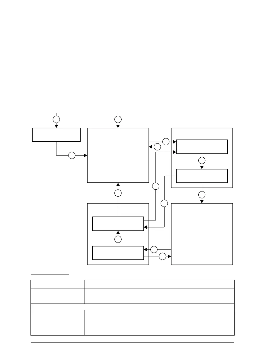
Brake state diagram
State descriptions
State name Description
BRAKE DISABLED Brake control is disabled (parameter 44.06 Brake control enable = 0, and 44.01
Brake control status b4 = 0). The open signal is active (44.01 Brake control
status b0 = 1).
BRAKE OPENING
BRAKE OPENING WAIT Brake has been requested to open. The drive logic is requested to increase the
torque up to opening torque to hold the load in place (44.01 Brake control status
b1 = 1 and b2 = 1). The state of 44.11 Keep brake closed is checked; if it is not
0 within a reasonable time, the drive trips on a 71A5 Mechanical brake opening
not allowed fault
*)
.
BRAKE CLOSING
DELAY
BRAKE CLOSING WAIT
BRAKE DISABLED BRAKE OPENING
BRAKE OPENING WAIT
BRAKE OPENING
DELAY
BRAKE CLOSED
BRAKE OPENBRAKE CLOSING
(from any state)
1
(from any state)
2
3
4
5
6
6
6
7
8
9
3
10

 Loading...


