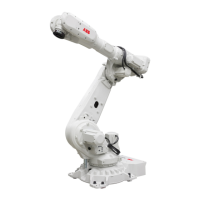
Hole configuration, base
This illustration shows the hole configuration used when securing the robot.
4x 306
4x 45
8x M20
4x
90°
4x
15°
52.5°
4x 325
800
45°
L
L
K
K
01
01
C
L
Axis 1
A
J
I
I
4x
45 H8
8x
5
3
8x
30
16
4x
3x45
8x 49.5
SECTION L-L
0.12
0.3
A
0.3
B
B
20 ( 25 H8)
25 H8
30
SECTION K-K
0.12
0.3
A
25 H8
+
0.033
0
2x R12.5
27 ±0.2
R400
DETAIL J
0,3
A
C
0,4
A
27
20
30
SECTION I-I
C
xx2100000788
74 Product manual - IRB 5720
3HAC079195-001 Revision: A
© Copyright 2022 ABB. All rights reserved.
3 Installation and commissioning
3.3.4 Orienting and securing the robot
Continued