Mechanical installation
Geometric adjustment of track motion
2-14 3HEA 800 970-001 Rev. D, Mars 2006
Installation and operation
Method 2
Adjustment of the track motion with position measurement equipment for
adjustment of the carriage horizontally along the entire travel length.
Action Info/Illustration
1. Position the track motion at the desired
position on the adjustment plates.
• Position the leveling plates on one
side of the intended installation
location.
• Position the bottom plates for the
cable tray modules on the other side
of the installation location.
• The spacing between the centers of
the plates should be 1000 mm.
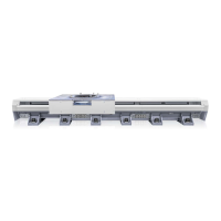
2. Place the prism in one of the mounting
holes. See Figure 7.
3. Move the carriage to position X-zero. Vernier scales against one another.
4. Move the entire track motion to the
correct X-zero and Y-zero position.
5. Use a spirit level to attain the horizontal
level (Z-value) by adjusting the
adjustment bolts.
6. Mounting hole measurement from robot
center.
Same center-point for in-line and 90° robot
position
1
0
0
0
x
N
1
0
0
0
±
1
m
m
1
0
0
0
 Loading...