Mechanical installation
Geometric adjustment of track motion
2-16 3HEA 800 970-001 Rev. D, Mars 2006
Installation and operation
Method 3
Method 3 is based on the available geometric system layout. This requires a laser
adjustment instrument for installation.
IRBT 6003S
Method 3 should be used if the robot is already installed on the track motion.
Action Info/Illustration
1. Determine coordinate system at
installation location for the track motion.
Place the track motion on the adjustment
plates at the position provided by the
simulation.
Use the track motion's zero-point on the
X-axis as reference.
The value on the X-axis increases from
the zero-point along the motion.
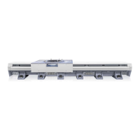
Figure 8 shows the zero-point with the
vernier scale placed on the opposite side of
the cable chain.
Due to the end cover plates and the tolerance chain, the dimension (739 mm) varies by ±8 mm
when the track motion is at position X-zero.
layout åkvagn.wmf
Figure 8 Carriage layout 6003S
Item Description Item Description
1 Vernier scale 3 X positive direction
1
4
3
2
 Loading...