Section 5 Electrical Test
Abbott VP 2000™ Processor Service Manual 5-39
30-608308/R1—September 2008
Electrical Test
1. Place the UUT power switch in the OFF position.
2. The test and setup checklist furnished with the unit will
identify the AC power input requirements for the unit.
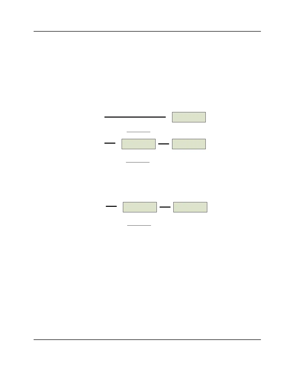
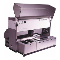
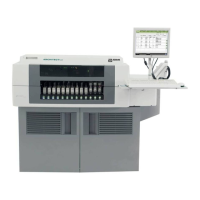
Hook up the UUT per the applicable diagram below. Insert
a stiff piece of card stock at each interlock switch location.
Figure 5.24: 117/110 VAC UUT
Figure 5.25: 230 VAC UUT
3. Place the UUT power switch to the ON position. Verify
that control panel “LEDs” display all “8 88 88 8888” and
that all the indicators on the keypad are ON.
When the “eights” disappear, the Robotic Arm should
move from whatever bath it is in and go to Bath 1 (unless
it is already there). A “1” should appear in the bath
position. Verify the fan in the rear of the UUT is running
and the READY indicator is ON.
UUT
UUTVARIAC
117 VAC
Receptacle
117 VAC
Receptacle
117 VAC UUT
100 VAC UUT
UUT
117/230 VAC
ADAPTOR
117 VAC
Receptacle
230 VAC UUT