SWITCH INSTALLATION
11
ensuring electromagnetic compatibility in other environments due to conducted as well as
radiated disturbance.
This equipment is supplied as open-type equipment. It must be mounted within an enclo-
sure that is suitably designed for those specific environmental conditions that will be present
and appropriately designed to prevent personal injury resulting from accessibility to live
parts. The enclosure must have suitable flame-retardant properties to prevent or minimize
the spread of flame, complying with a flame-spread rating of 5VA, V2, V1, V0 (or equivalent)
if nonmetallic. The interior of the enclosure must be accessible only by the use of a tool.
Subsequent sections of this publication might contain additional information regarding spe-
cific enclosure-type ratings that are required to comply with certain product safety certifica-
tions.
2.3.1 Connecting Hardware
In this instruction, it will explain how to find a proper location for your Modbus Gateways,
and how to connect to the network, hock up the power cable, and connect to the EKI-7428G
Series.
2.4. Verifying Switch Operation
Before installing the device in a rack or on a wall, power on the switch to verify that the
switch passes the power-on self-test (POST). To connect the cabling to the power source
see “Power Supply Installation” on page 15.
At startup (POST), the System LED blinks green, while the remaining LEDs are a solidy
green. Once the switch passes POST self-test, the System LED turns green. The other
LEDs turn off and return to their operating status. If the switch fails POST, the System LED
switches to an amber state.
After a successful self-test, power down the switch and disconnect the power cabling.
The switch is now ready for installation on its final location.
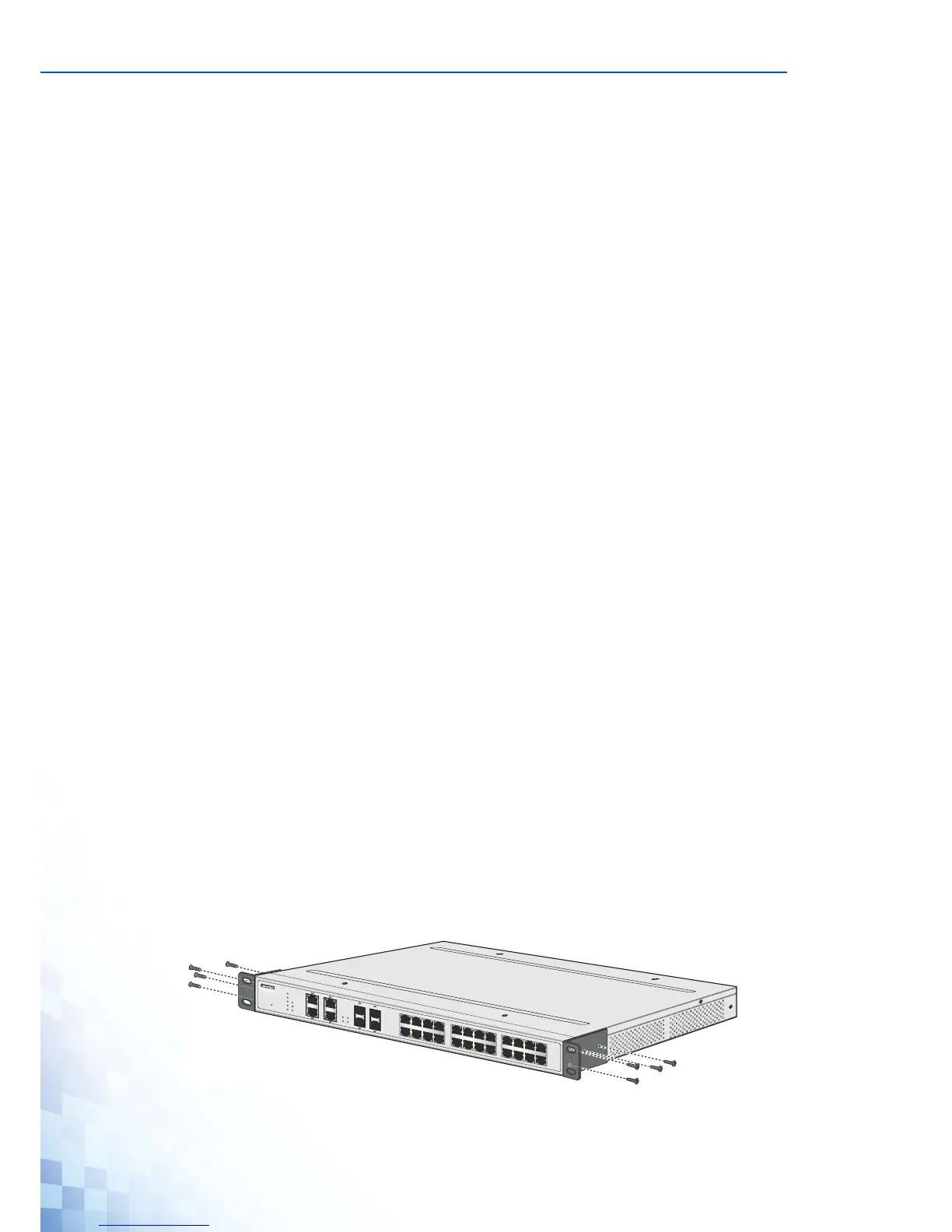
2.5. Installing the Switch
2.5.1 Rack-Mounting
1. Align the rack mount brackets with the holes on the switch.
2. Secure the rack mount brackets with the provided screws.
Figure 2-1. Installing the Rack Mount Brackets
 Loading...