SWITCH INSTALLATION
19
By connecting the ground terminal by drain wire to earth ground the switch and chassis can
be ground.
2.9.4 Wiring a Relay Contact
The following section details the wiring of the relay output. The terminal block on the EKI-
7428G Series is wired and then installed onto the terminal receptor located on the EKI-
7428G Series.
Figure 2-14. Terminal Receptor: Relay Contact
The terminal receptor includes a total of six pins: two for PWR1, two for PWR2 and two for a
fault circuit.
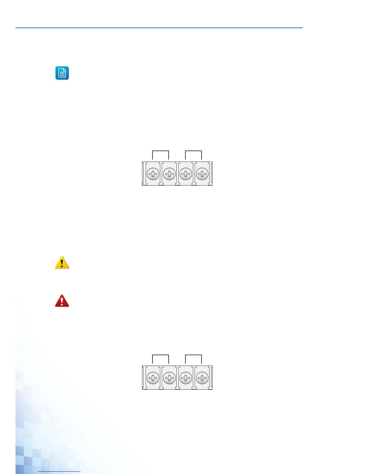
2.9.5 Wiring the Power Inputs
There are two power inputs for normal and redundant power configurations. The power
input 2 is used for wiring a redundant power configuration. See the following for terminal
block connector views.
Figure 2-15. Terminal Receptor: Power Input Contacts
To wire the power inputs:
Before applying power to the grounded switch, it is advisable to use a volt meter to
ensure there is no voltage difference between the power supply’s negative output
terminal and the grounding point on the switch.
Do not disconnect modules or cabling unless the power is first switched off.
The device only supports the voltage outlined in the type plate. Do not use any
other power components except those specifically designated for the switch device.
POWER DOWN AND DISCONNECT THE POWER CORD BEFORE SERVICING OR WIRING THE
SWITCH.

 Loading...