SWITCH INSTALLATION
20
Make sure the power is not connected to the switch or the power converter before proceed-
ing.
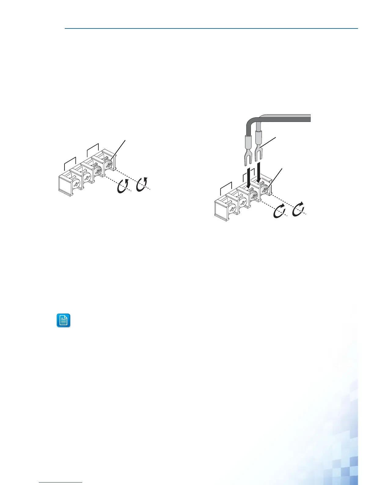
1. Insert a small flat-bladed screwdriver in the V1+/V1- wire-clamp screws, and loosen the
screws.
2. Insert the negative/positive DC wires into the V+/V- terminals of PW1. If setting up
power redundancy, connect PW2 in the same manner.
3. Tighten the wire-clamp screws to secure the DC wires in place.
Figure 2-16. Installing DC Wires in a Terminal Block
2.10. Reset Button
Reset configuration to factory default:
Press and hold Reset button for 5 seconds.
System reboot:
Press and hold Reset button for 2 seconds.
Do NOT power off the Ethernet switch when loading default settings.
 Loading...