Home
ADVANTEST
Measuring Instruments
R3131
ADVANTEST R3131 User Manual
4
of 1
of 1 rating
261 pages
Give review
Manual
Specs
To Next Page
To Next Page
To Previous Page
To Previous Page
Loading...
R3131 Spectr
um Analyzer Operation Man
ual
2.4 Other
Functions
2-100
Aug 28/98
Figure 2-96 Screen Showing the Date being Set
Setting th
e time
5.
Press
Hour
,
1, 3
and
Hz(ENTE
R)
The time is set to 1pm.
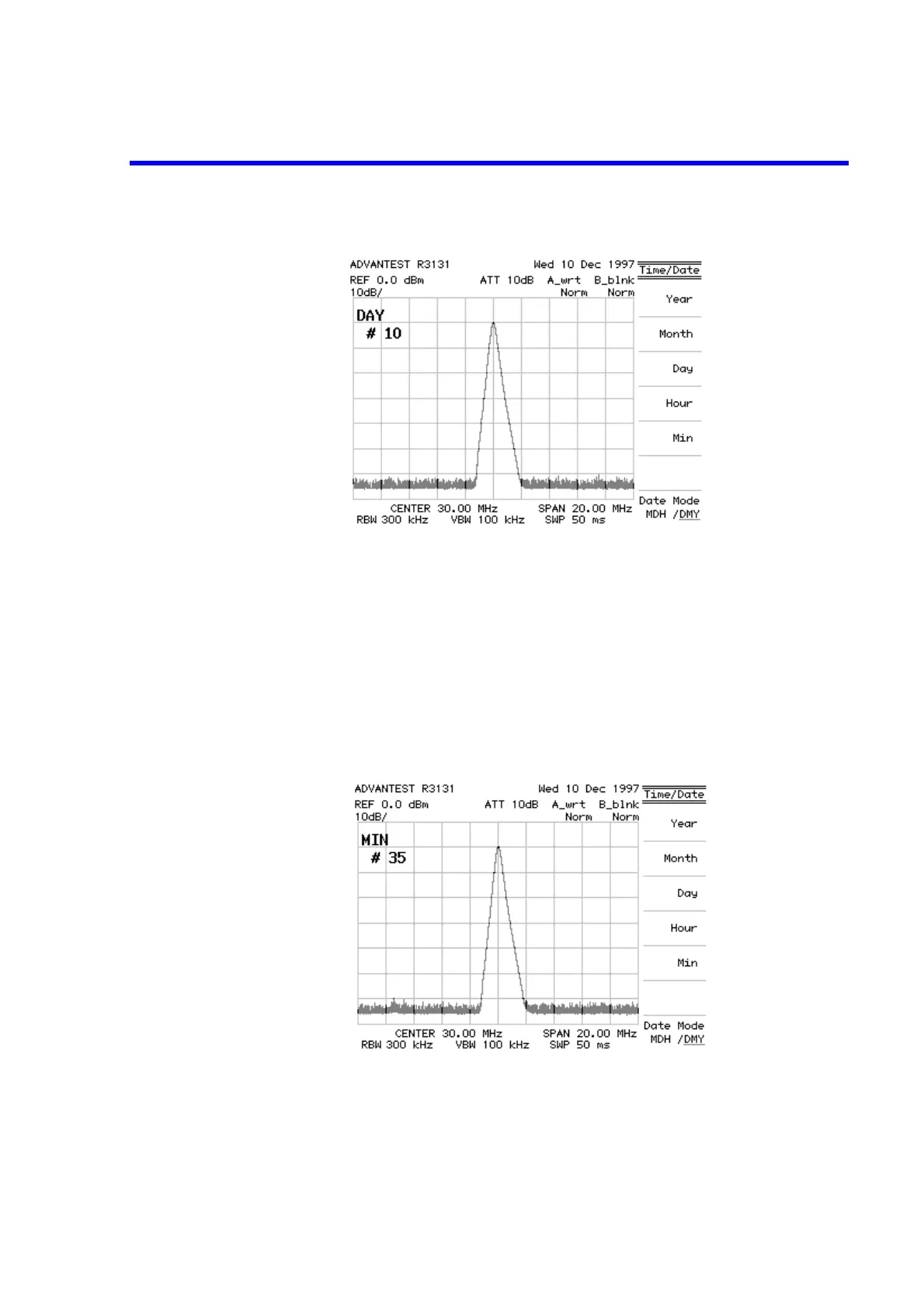
6.
Press
Min
,
3, 5
and
Hz(E
NTE
R)
.
The time is set to 1:35pm.
Figure 2-97 Screen Showing the Hour being Set
124
126
Table of Contents
Table of Contents
4
Introduction
14
Product Description
14
Accessories
15
Standard Accessories List
15
Power Cable Options
16
Operating Environment
17
Environmental Conditions
17
Power Requirements
18
Power Fuse
18
Power Supply Specifications
18
Replacing the Power Fuse
19
Power Cable
20
System Checkout
21
Connecting the Power Supply Cable
21
Screen Display after Self Tests Have Completed
22
Self Test Screen
22
Screen Shown after Executing Self Test
23
Cleaning, Storing and Transporting the R3131 Spectrum Analyzer
24
Cleaning
24
Removing the Display Filter
24
Storing
25
Transporting
25
Operation
26
Panel Description
26
Front Panel
26
Screen Annotation
35
Rear Panel
37
Basic Operation
39
Operating Menus and Entering Data
39
Displaying Spectrums and Operating the Markers
42
Factory Defaults Screen
43
Calibration Signal Output Screen
43
Active Area Display
44
Setting the Center Frequency
44
Measuring Settings Screen
45
Peak Search Display Screen
46
Frequency Difference between the Peak Point and a Point 3 Db Levels down
47
Frequency Difference between the Peak Point and a Point 60 Db Levels down
47
Measuring Window and the Display Line
48
Factory Defaults Screen
48
Calibration Signal Output
49
Measuring Settings Screen
49
Activating the Display Line
50
Making a Comparison between Peaks Using Reference Lines
51
Screen Display Showing the Measuring Window
52
Screen Display after Zoom in
52
Measuring Frequency Using Counter
53
Factory Defaults Screen
53
Calibration Signal Output Screen
54
Measuring Settings Screen
54
Frequency Counter Measurement (Resolution: 1 Khz)
55
Frequency Counter Measurement (Resolution: 10 Hz)
55
Auto Tuning
56
Screen Display Prior to Auto Tuning
56
Screen Display after Auto Tuning
57
Tracking Operations
58
Signal Tracking Screen
59
Continuous Peak Search Screen
60
UNCAL Messages
61
Measuring Settings Screen
62
Screen with UNCAL Message
62
Normal Measurement Screen
63
Separating Two Signals
64
Setup for Measuring Two Signals Separately
64
Two Superimposed Peaks
65
Two Discernible Peaks
66
Two Distinct Peaks Can Now be Seen
66
Dynamic Range
67
Setup for Verifying the Dynamic Range
67
Screen Display Prior to Changing the RBW
68
Screen Display after Changing the RBW
69
Screen Display after Changing the VBW
69
The Trace after Averaging
70
2.2.10 Input Saturation
71
Setup for Input Saturation
71
Screen Display Without Saturation
72
Screen Display Showing Saturation
73
2.2.11 Harmonic Distortion
74
Setup for Measuring Harmonic Distortion
74
Screen Display Showing Harmonic Distortion
75
Screen Display Showing Reduced Harmonic Distortion
76
2.2.12 Intermodulation
77
Setup for Measuring Intermodulation
77
Screen Display Showing Intermodulation Distortion
78
Screen Display Without Intermodulation Distortion
79
2.2.13 Calibration
80
Screen Display Showing the Cal Menu
80
2.2.14 Entering User-Definable Antenna Correction Data
81
Editing the Correction Data Table
82
Screen Display Showing the User-Definable Correction Data Table
83
Measurement Examples
84
Measuring the Channel Power
84
Setup for Measuring the Channel Power
84
Setting the Offset Level
85
Setting the Measuring Window
86
Measuring the Channel Power
86
Measuring the Occupied Bandwidth (OBW)
87
Setup for Measuring the Occupied Bandwidth
87
Setting the Detector Mode
88
OBW Measurement Screen
89
OBW(95%) Measurement Screen
89
Measuring Adjacent Channel Leakage Power (ACP)
90
2.3.3.1 Measurements Using the ACP POINT Method
90
Setup for Measuring the Adjacent Channel Leakage Power
90
Setting the Specified Bandwidth
92
Measurement of the Adjacent Channel Power (ACP POINT)
92
2.3.3.2 Measurements Using the ACP GRAPH Method
93
Setup for Measuring the Adjacent Channel Leakage Power
93
Displaying a Graph as a Result of Operation
95
Adjacent Channel Leakage Power Measurements (ACP GRAPH)
95
Measuring the VA Ratio
96
Setup for Measuring the VA Ratio
96
Performing Max Hold
97
Measuring the Video Carrier Level
98
Measuring the Audio Carrier Level
98
Pass-Fail Judgments
99
Setup for the Pass-Fail Judgment
99
Pass-Fail Measurement Screen
100
Level Window Setting Screen
101
Measuring Window Screen
101
Harmonic Distortion Measurements
103
Setup for Measuring the Harmonic Distortion
103
Measuring the Fundamental Wave
104
Measuring the Harmonic Distortion
105
Measurements Using TG (Option 74)
106
Setup for TG Measurements
106
Measurement Screen after a Normalization Calibration
107
Connecting the Unit under Test
108
Insertion Loss Measurement Screen
109
Other Functions
110
Using Floppy Disks
110
Floppy Disk Write Protection
110
Screen for the F.disk Menu
112
Saving or Recalling Data
113
Screen Display Showing Floppy Disk as the Destination
113
Display for Selecting the Data to be Saved
114
Display after Data Has Been Saved to a File
115
Screen Display Showing File Protection Enabled
116
Screen Display Showing the Selected File
117
Screen Display Showing Recalled Data
117
Screen as Shown When Deleting a File
118
Screen as Shown after Deleting File Data
119
Outputting Screen Data
120
Screen Display Showing Floppy Disk as the Specified Destination
120
Recommended Compatible Printers
121
Printer Specification Screen Display
122
Printer Setup Screen
123
Setting Date and Time
124
Time/Date Menu
124
Screen Showing the Date Being Set
125
Screen Showing the Hour Being Set
125
Menu Index
128
Menu Map
134
Menu Function Descriptions
143
AUTO TUNE Key (Auto Tuning)
143
BW Key (Bandwidth)
144
CAL Key (Calibration)
145
CONFIG Key (Configuration)
146
COPY Key (Hard Copy)
148
COUNTER Key (Frequency Counter)
149
DISPLAY Key (Line and Window)
150
EMC Key (EMC Measurement)
153
FREQ Key (Frequency)
155
3.3.10 Hold Mode
156
LEVEL Key (Frequency Level)
157
LOCAL Key (GPIB Remote Control)
159
MEAS Key (Measurement)
160
MKR Key (Marker)
162
MKR → Key (Marker →)
165
PAS/FAIL Key (Pass-Fail Judgment)
167
PK SRCH Key (Peak Search)
168
POWER MEASURE Key (Power Measurement)
169
Obw
170
PRESET Key (Initialization)
171
RECALL Key (Data Readout)
172
REPEAT Key (Continuous Sweep)
173
SAVE Key (Saving Data)
174
SELF TEST Key (Self Test)
175
SINGLE Key (Single Sweep)
176
SPAN Key (Frequency Span)
177
SWEEP Key (Sweep Time)
178
TG Key (Tracking Generator) (Option 74)
179
TRACE Key (Trace Data)
181
TRIG Key (Trigger)
183
Setting Values
184
Set Resolution
184
Center Frequency Set Resolution Vs. Frequency Span
184
Frequency Span Set Resolution Vs. Frequency Span
184
Set Values for RBW, VBW and SWP Time
185
Values for RBW, VBW and SWP Time (Using AUTO)
185
Factory Defaults
186
Resolution Bandwidth
186
Defaults Configuration Values
187
Values for Default Config
187
Remote Programing
188
GPIB Remote Programming
188
GPIB Setup
188
GPIB Interface Functions
190
Responses to Interface Messages
190
Message Exchange Protocol
192
Command Syntax
193
Data Formats
193
Status Bytes
195
Arrangement of the Three Status Registers
196
Details of the Three Status Registers
197
Structure of the Status Byte Register
199
GPIB Command Codes
201
Sweep Mode
203
Sweep Time
203
Frequency
204
Peak Search
205
Pass-Fail Judgment
209
Auto Tuning
209
Power Measurement
210
Data Save/Recall
213
Hard Copy
215
Status Bytes
215
Data Input
217
4.1.10 Basic Programming
218
Data Output Format (Talker)
220
4.1.12 Trace Data I/O
224
4.1.13 Using the Status Byte
229
Remote Control Function
233
GPIB and RS-232 Compatibility
233
Features of RS-232 Remote Control
233
Parameter Setup Window
233
Connection between the Controller and the Spectrum Analyzer
234
Cable Wiring Diagram
235
Data Format
236
Differences between RS-232 and GPIB
237
Panel Control
237
Remote Control Usage Examples
237
Specifications
238
Appendix 1 Error Message
244
Appendix 2 Glossary A2-1
248
Reference Level
248
Spurious Response
250
Noise Sidebands
250
Bandwidth Selectivity
251
Bandwidth Switching Accuracy
252
Dimensional Outline Drawing
254
Alphabetical Index
256
4
Based on 1 rating
Ask a question
Give review
Questions and Answers:
Need help?
Do you have a question about the ADVANTEST R3131 and is the answer not in the manual?
Ask a question
ADVANTEST R3131 Specifications
General
Brand
ADVANTEST
Model
R3131
Category
Measuring Instruments
Language
English
Related product manuals
ADVANTEST R3131A
12 pages
ADVANTEST R3131 Series
276 pages
ADVANTEST R3162
588 pages
ADVANTEST R3765G Series
446 pages
ADVANTEST TQ8210
37 pages