R3131 Spectrum Analyzer Operation Manual
2.2 Basic Operation
2-52 Apr 10/98
2.2.12 Intermodulation
This section describes how to set up the attenuator (ATT) when using a spectrum analyzer which is
receiving more than one input signal.
When signals with an excess amplitude are input, spurious signals produced by intermodulation are
displayed. It is important that the ATT be adjusted to moderate the mixer input.
Setup
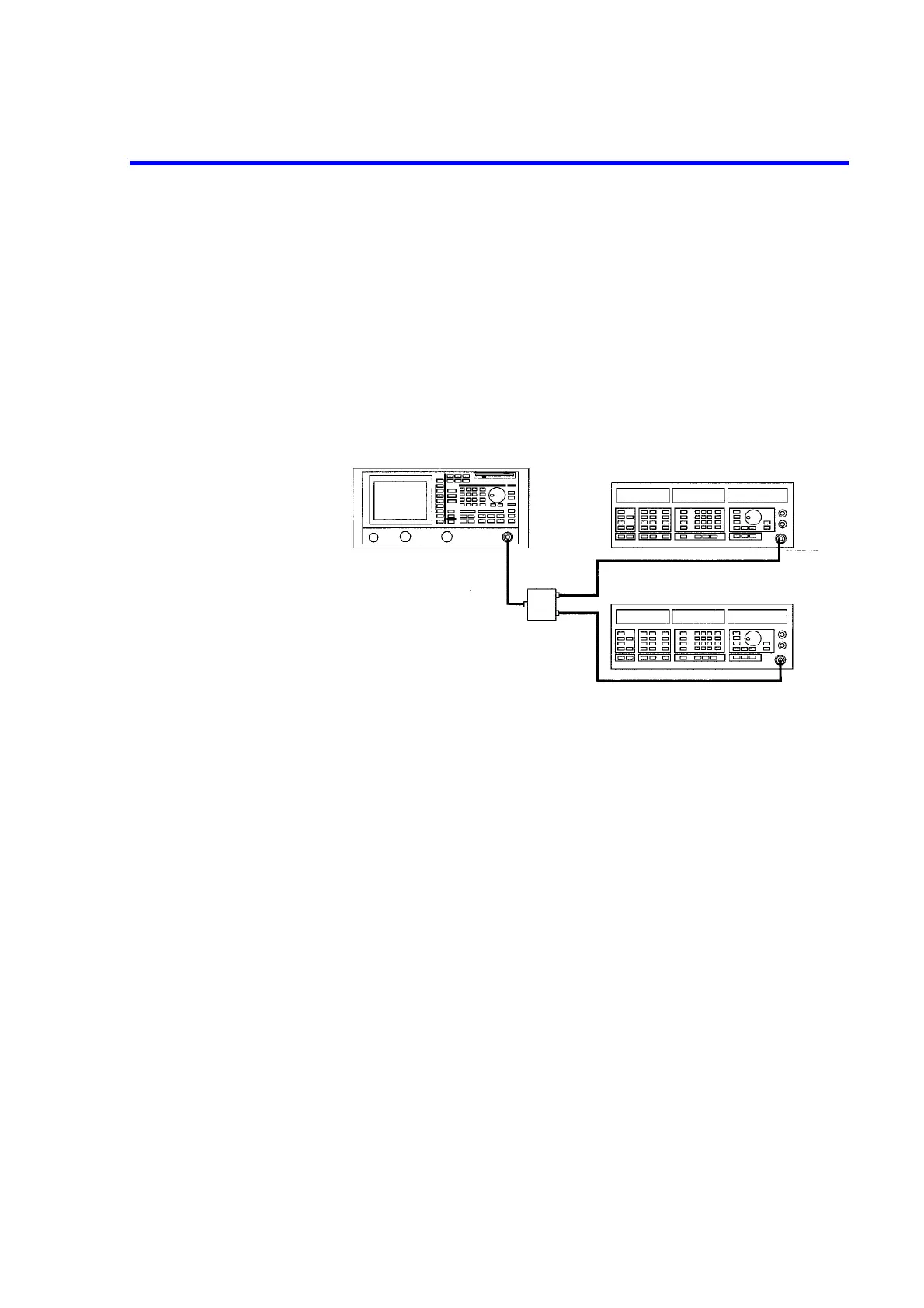
1. Connect the signal generators as shown in Figure 2-46.
Figure 2-46 Setup for Measuring Intermodulation
Power on
2. Turn the power on.
Setting the signal generators
This prepares the signal generator outputs.
3. Set SG1 as follows: the frequency to 200.0 MHz; level to -4 dBm; modulation
to non-modulated mode; and output to ON.
4. Set SG2 as follows: the frequency to 200.2 MHz; level to -4 dBm; modulation
to non-modulated mode; and output to ON.
Each signal has an input level of -10 dBm.
Initialization
This resets the current settings to the factory defaults.
R3131 Spectrum analyzer
Signal generator (SG1)
Signal generator (SG2)
Power combiner
(Insertion loss: 6 dB)
OUTPUT
connector
OUTPUT
connector
RF INPUT 1
connector