R3131 Spectrum Analyzer Operation Manual
2.1 Panel Description
2-12 Oct 28/98
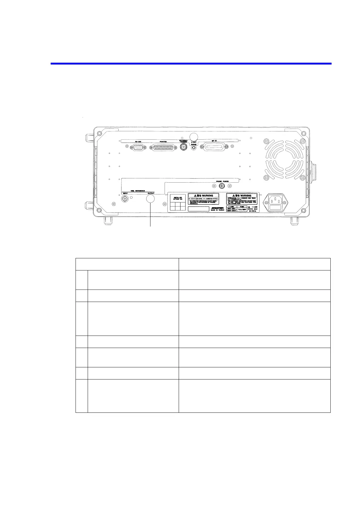
2.1.3 Rear Panel
This subsection shows the rear panel and describes its terminals and connectors.
Figure 2-3 Rear Panel
Control Description
1 RS-232 connector Connector for an external unit used to control the spectrum
analyzer through an RS-232 interface
2 PRINTER connector Connector used when attaching a Centronix printer
3 EXTERNAL TRIGGER
terminal
Approximately 10 kΩ input impedance; starts sweeping at
the leading or trailing edge (selectable) of the TTL level
input signal. This signal can be used as the gated sweep sig-
nal source.
4 X-OUT terminal (unused)
5 PHONE connector Connector for an 8Ω earphone used for AM/FM demodu-
lated audio output
6 GPIB connector Connector for an external controller cable
7 Exhaust vent Used to vent excess heat buildup in the spectrum analyzer
–––––––––––––––––––––––––––––––––––––––––––––––
CAUTION: Do not block this vent
–––––––––––––––––––––––––––––––––––––––––––––––
 Loading...

