R3131 Spectrum Analyzer Operation Manual
5 SPECIFICATIONS
5-3Sep 24/98
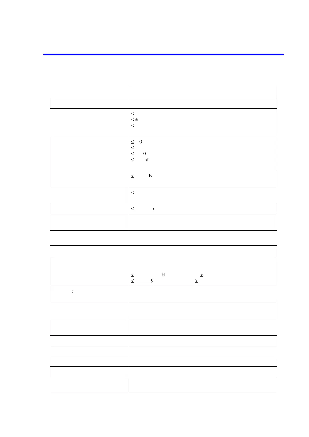
(5) Amplitude Accuracy
(6) Input/Output
Characteristics Description
Calibration signal 30MHz, -20dBm ± 0.3dB
Frequency response
>
± 0.5dB (100kHz to 3GHz, ATT = 10dB)
>
± 1dB (100kHz to 2GHz)
>
± 2dB (9kHz to 3GHz)
(after the calibration, and in reference to 30MHz)
Scale indication accuracy
Logarithmic
Linear
>
± 0.5dB, (0 to -20dB) (after self calibration)
>
± 1.5dB/70dB (after self calibration)
>
± 1.0dB/10dB (after self calibration)
>
± 0.2dB/1dB (after self calibration)
within ± 5% of the reference level
Input attenuator switching accu-
racy
>
± 0.3dB (0 to 50dB)
(in reference to an attenuation of 10dB at 30MHz)
Resolution bandwidth switching
accuracy
>
± 0.5dB (after self calibration)
IF gain error
>
± 0.5dB (after self calibration)
Overall level accuracy
±
1.5dB (REF = -50 to 0dBm, ATT = 10dB, 2dB/div,
RBW = 300kHz, f > 100kHz, after self calibration)
Characteristics Description
RF input
Connector/Impedance
VSWR
N-type female, 50Ω (nominal)
>
1.5 (100kHz to 2GHz, ATT
P
10dB)
>
2.0 (9kHz to 3GHz, ATT
P
10dB)
10 MHz reference input
Input range
BNC female, 50Ω
-10dBm to + 10dBm
External trigger input BNC female, 10kΩ (nominal), DC connection
Refer to item (7) for the external gate signal specifications.
Phone output Small size monophonic female
8Ω
GPIB interface IEEE-488 bus connector
Serial interface D-SUB 9 pin
Printer interface D-SUB 25 pin, ESC/P, ESC/P-R, PCL
Floppy drive 3.5 inch, MS-DOS format
Probe power supply output voltage
+12.4V, -12.4V
(Maximum output current: 100mA for each voltage source)
 Loading...

